
R2-D2 Part 14: left and right Legs
In Part 14 of my R2-D2 build, I tackle the left and right legs, printing and assembling the main sections, ankles, cylinders, alignment pins and detailed components.

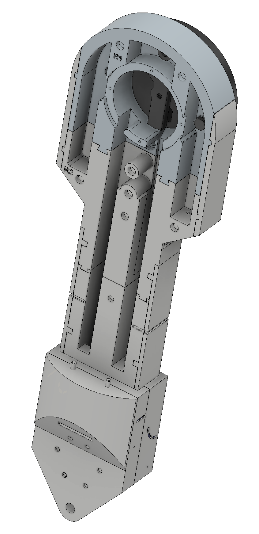
With the body, skirt, centre foot and all the smaller details now complete, it was finally time to move on to the legs. I decided to start with the left leg, although the overall construction is very similar to the right.
Although I'm focusing on the left leg here, I was actually printing both legs at the same time. Rather than completely finish one leg before starting the other, I printed the corresponding parts together — left and right top shoulders, then the left and right lower shoulders, and so on. This seemed like the most sensible way to keep the build progressing on both sides.
The first part I tackled was the top shoulder, which is the largest individual piece of the leg. Because of its size, it occupied almost the entire build plate on my Bambu Lab A1. Large prints like this can be a little nerve-wracking, as any warping or loss of bed adhesion could potentially ruin several hours of printing.
To give it the best chance of staying firmly attached, I used both an inner and outer brim. This meant there was more material to remove afterwards, but for a print this large, I thought the extra bed adhesion was well worth it.
The print took around six hours, but thankfully it came out really well. Removing the brim took a little patience, particularly around the edges, so I took my time with a utility knife to avoid damaging the actual part.
This is actually the first photo I took of the left leg, as I didn't take a picture of the top shoulder on its own. By the time I took the photo, I'd already moved on to fitting it to the next section, so it shows the two parts together rather than the shoulder as a standalone piece.
Once it was cleaned up, I had the first major component of the left leg ready for assembly.
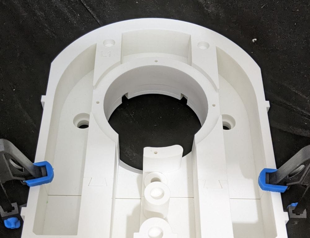
This is actually the first photo I took of the left leg, as I didn't take a picture of the top shoulder on its own. By this point, I'd already moved on to fitting it to the next section, so the photo shows the two parts together rather than the shoulder as a standalone piece.
There was, however, a small complication with the leg configuration that I wouldn't discover until much later in the build.
At the time, I had understood that building the legs in the 2-3-2 configuration required the longer ankle and booster parts, so that's the route I initially went down. It seemed like the logical choice based on what I understood from the instructions, and because I was printing both the left and right legs at the same time, I printed the longer versions for both.
It was only much later that I discovered the longer parts were actually intended for the motorised version of the 2-3-2 configuration. The standard leg parts can also be used for a manually operated 2-3-2 setup, which is what I'm building.
Had I known that from the start, I would have printed the standard versions instead. Unfortunately, by the time I realised my mistake, I'd already printed a considerable number of the longer parts for both legs. That meant a fair amount of printing time and quite a lot of filament had already gone into parts that weren't actually necessary for my setup.
At that point, I had already made too much progress to simply throw everything away and start again. I decided to carry on with the parts I'd already printed and see how they worked in practice. If they cause problems later, I can always reprint the standard versions, but for now there didn't seem to be much point in wasting everything I'd already produced.
It's one of those things that is easy to miss when you're working through a large project like this. There are a lot of parts, options and configurations, and sometimes you don't discover exactly how everything fits together until you're well into the build.
For now, though, I was concentrating on getting the main leg structure printed and prepared. With the large top shoulder successfully completed, it was time to move on to the next component.
The next parts were the lower shoulders. As I was printing both legs alongside each other, I printed the left and right lower shoulders together as a pair. These were another fairly large print, with each one taking around five hours, so this was another sizeable chunk of printing time and filament.
Unlike the top shoulders, the lower shoulders had several overhangs that required supports. For the supports, I again used PETG for the support interface, which made them much easier to remove without damaging the printed parts. I also added a brim to help keep each print firmly attached to the build plate and reduce the chance of warping during the five-hour prints.
Once both prints were finished, I cleaned up the supports and removed the brims, leaving the two lower shoulders ready to be joined to their corresponding upper shoulders.
I didn't take photos of the lower shoulders on their own, but I did take one once the two sections had been glued together. For the assembly, I used clear Gorilla Glue, which gave me around 20 minutes of working time. This was useful here, as it gave me enough time to get each lower shoulder properly aligned with its upper section before the glue started to set.
I used clamps to hold the two sections firmly together while the glue cured. With everything clamped in place, both shoulder assemblies could be left to set without having to worry about the parts moving out of alignment.
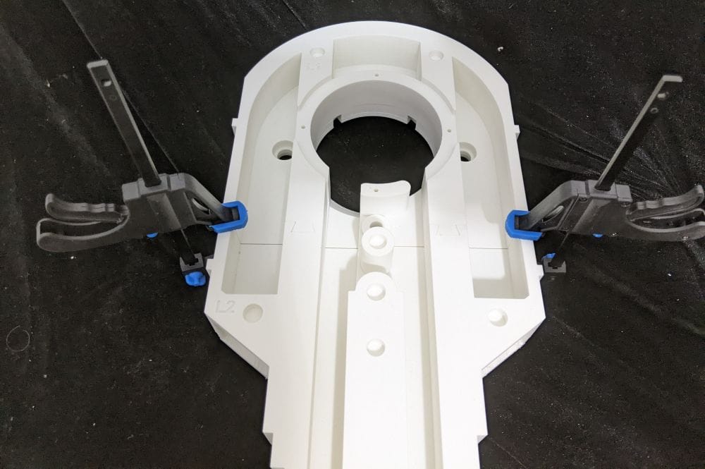
This was the first major section of the left leg to really start looking like part of the finished assembly, and with the upper and lower shoulders joined together, I could move on to the next component.
The next parts were the lower legs. These were smaller pieces than the two shoulder sections, with each one taking around three hours to print. As I was building both legs in parallel, I printed the left and right lower legs together, adding another six hours of printing time to the build.
There was a small channel underneath each part which probably didn't strictly need supports, but I decided not to take any chances. I added supports anyway, using the same PETG support interface as before to make them easier to remove. I also added a brim to help keep the parts securely attached to the build plate throughout the prints.
Once both prints were finished, I cleaned everything up and they were ready to join the shoulder assemblies.
Again, I didn't take photos of the lower legs on their own. The next photo I took was once they had been glued to the other two sections, so this was the point where the main structure of both legs really started to come together.
I used the same clear Gorilla Glue as before, with its 20-minute working time giving me enough time to get everything aligned properly. I then used clamps to hold the three sections of each leg firmly together while the glue cured.
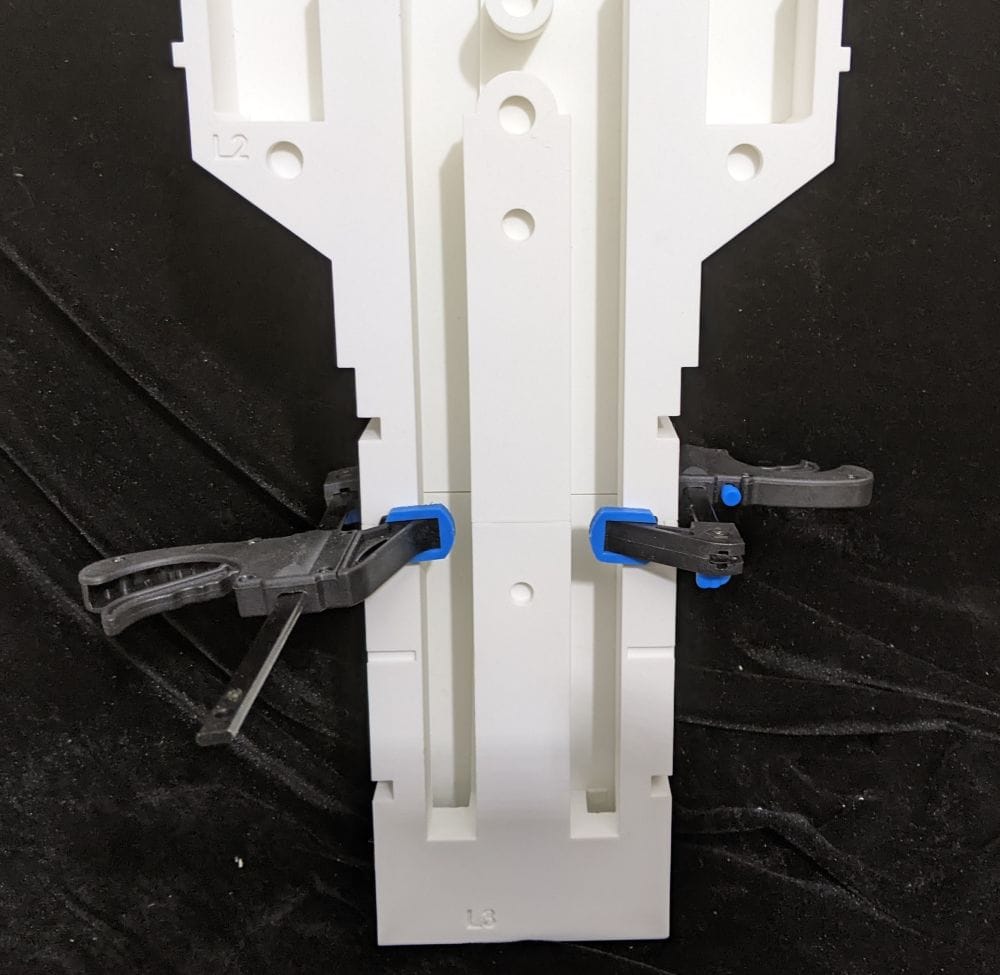
Seeing these three pieces joined together for the first time gave me a much better idea of the overall size and shape of the finished leg. There was still plenty more to add, but the basic structure was now starting to look like an actual R2-D2 leg.
While I was waiting for the glue to dry, I moved on to a few of the smaller parts. I printed four bolt inserts along with the Y-shaped centre leg bracket, which fits into the hole in the shoulder hub.
It was only later that I discovered the centre leg bracket was actually no longer required for the version I was building. By that point, however, I'd already printed it, so rather than leave it sitting in a box of unused parts, I decided to go ahead and fit it anyway.
As it turned out, that decision wasn't a complete waste. The bracket would actually come in handy later on when I made a small modification of my own to the build.
At this stage I didn't know that yet, of course, so for the time being it was simply another part to clean up and add to the growing collection of leg components.
Next up were the four alignment plates that wrap around the edges of the leg. These help hold the main sections together while also adding some much-needed structural strength to the overall assembly.
As the four plates for each leg are relatively small, I printed them together as a single batch. I started with the four plates for the left leg, then printed the four corresponding plates for the right leg. I still used a brim for each print, as I wanted to make sure the pieces stayed firmly attached to the build plate and remained as flat as possible throughout the print.
Once they were printed and cleaned up, it was time to fit them to the legs. I didn't take any photos of the plates on their own, so the next photo shows them fitted to the main leg assembly.
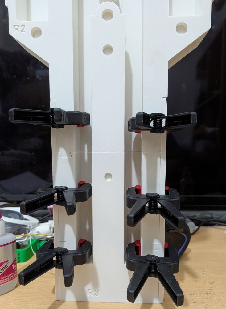
I used the same clear Gorilla Glue as before and, once again, used clamps to hold everything securely in position while the glue cured. The clamps were particularly useful here, as they kept the plates pressed firmly against the leg while I made sure everything was properly aligned.
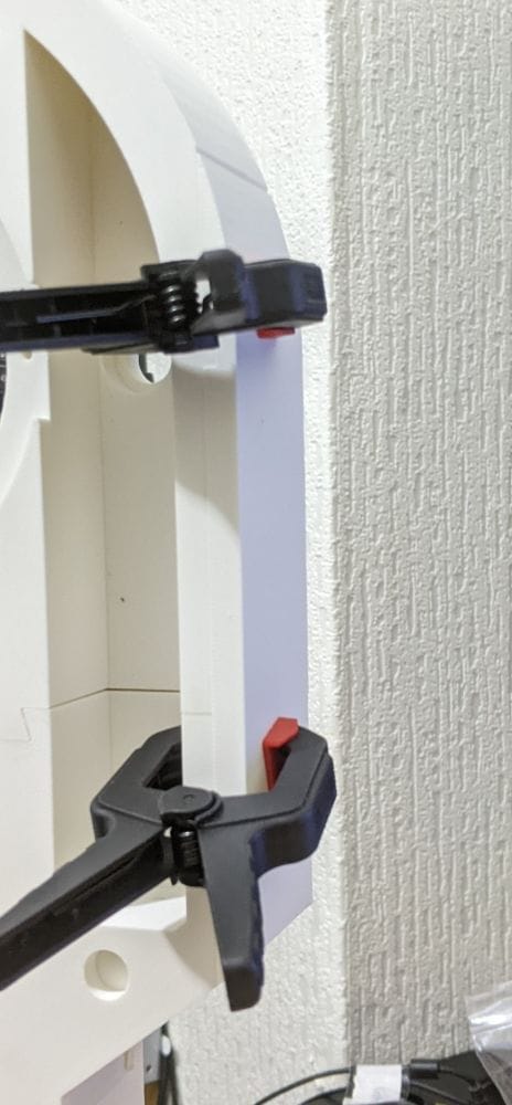
With the alignment plates in place, the main structure was becoming much more rigid and starting to look considerably more like a finished R2-D2 leg.
The next assembly was the horseshoe, which is made up of six separate printed parts for each leg. These are handed parts, so I had to be careful to keep the left and right versions separate and make sure I didn't accidentally mix them up when it came time to glue everything together.
All six pieces print flat on the build plate, so there weren't any complicated print orientations to worry about. I still added a brim to each part, though, as I wanted to minimise the chance of any warping while they were printing.
The parts also have a rib detail on the inside with an overhang, which meant there was a little bit of clean-up needed once the prints were finished. Nothing too troublesome, but it was worth taking the time to make sure the surfaces were clean before moving on to the assembly.
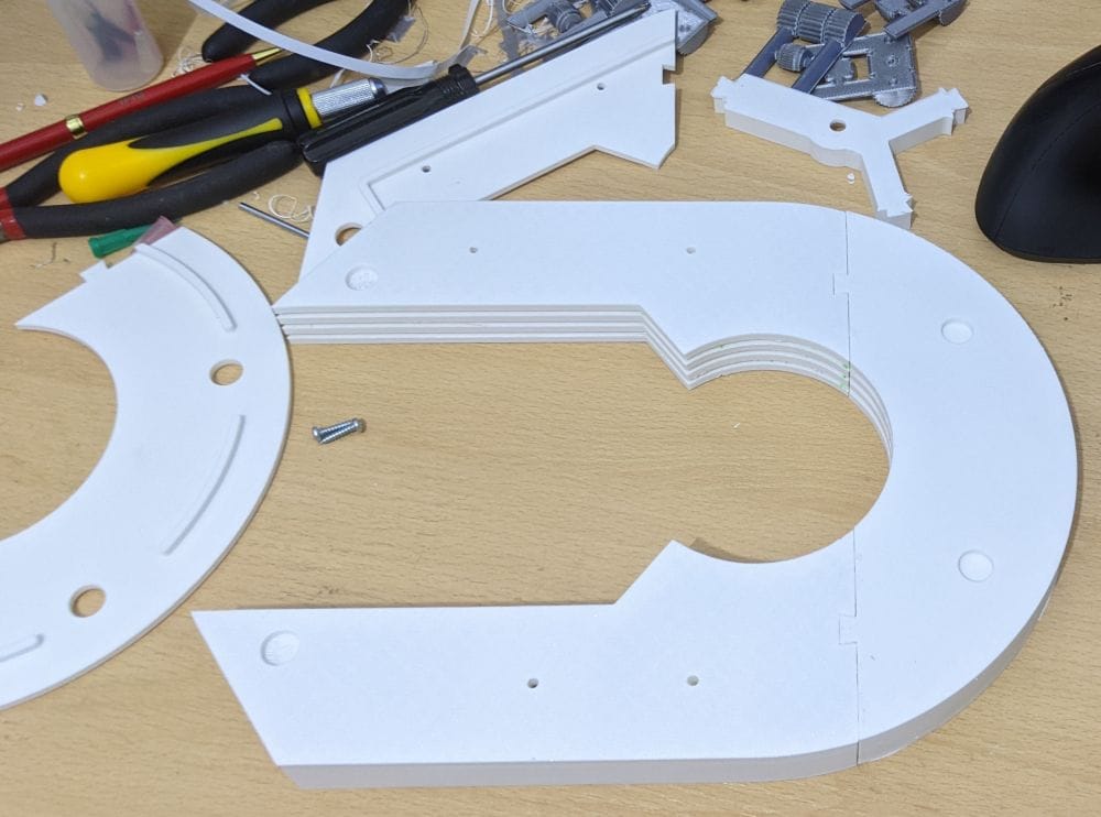
Once I'd worked out exactly how the six pieces fitted together, the test fitting was surprisingly straightforward. There are a few pieces to line up, but once I understood how they were supposed to go together, everything fitted together quite nicely.
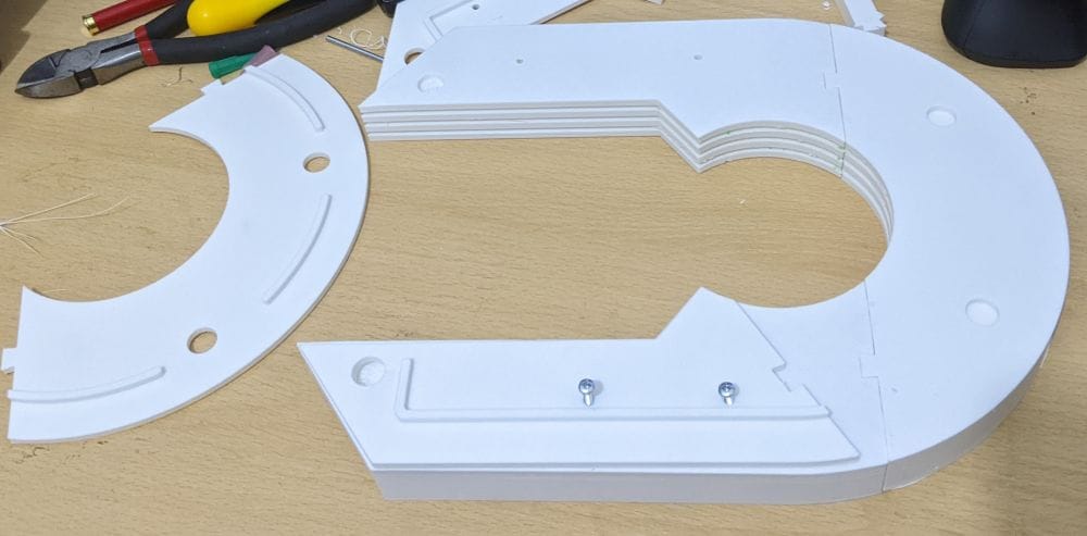
For the final assembly, I used BSI Maxi-Cure. I also used a couple of screws to temporarily hold the rear plate sections together while the glue set. This made it much easier to keep everything properly aligned and prevented the parts from shifting while the adhesive cured.
With the horseshoe assembled, I had another major component ready to eventually fit onto the leg.
The next parts I printed were the ankle components. This was where I finally discovered the mistake I'd made earlier with the leg configuration.
There are standard and long versions of the ankle, and I'd originally assumed that because I was planning to use the 2-3-2 configuration, I needed the long version. It was only when I looked into the differences more closely that I realised the two versions are actually the same overall size. The difference is in the internal recess.
The reason for the longer configuration is actually related to automated 2-3-2 systems. On those setups, the battery boxes can catch on the skirts as the droid switches between two and three legs, so the longer version provides additional clearance. Since my 2-3-2 conversion is manual, the standard ankle would have worked perfectly well.
So, this was the point where I realised I'd made an unnecessary choice earlier in the build.
By this stage, however, I'd already printed the long version. Rather than waste the filament and start reprinting the leg components I'd already completed, I decided to continue with the long setup and see how it performs over the longer term.
If it turns out to cause a problem, I can always go back and print the standard version later. For now, though, there didn't seem to be any reason to throw away perfectly usable parts simply because I'd misunderstood which version I needed.
It was a useful lesson, though: with a project this large, it's definitely worth understanding the reason behind the different options before committing to a particular version. Unfortunately, I only worked that one out after I'd already printed them!
The ankle itself is made up of three main parts: the Ankle Hinge, Ankle Back and Ankle Curve. I started with the Long Ankle Hinge, which was a fairly large but straightforward print. As with the other larger parts, I added a brim to help keep it firmly attached to the build plate.
I printed the Ankle Back and Ankle Curve in the same way, again using a brim on both parts. Once all three pieces had finished printing, I cleaned them up and checked the fit before moving on to the assembly.
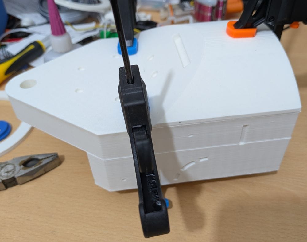
The three parts were then glued together using clear Gorilla Glue. Getting everything lined up wasn't particularly difficult, but clamping the assembled ankle was a little more challenging. There isn't a huge amount of convenient surface area to get a clamp onto, so it took a bit of juggling to get everything held in the right position.
Thankfully, I managed to get it clamped securely enough, and it held together well while the glue cured. While I was waiting for the glue to set, I moved on to printing the corresponding right-side ankle, keeping the two legs progressing alongside each other.
Once the clamps were removed, I had a solid ankle assembly ready for the next stage of the leg build.
With the main leg structure assembled and the ankle now glued together, I could finally test fit the two sections together. This was a useful check to make sure everything lined up correctly before moving on to the next stage.
I couldn't glue the ankle to the leg just yet, though, as there were still other parts that needed to be fitted into the assembly first. Gluing it in place at this stage would have made fitting those parts much more difficult, so for now I left the ankle as a test fit.
It was still a satisfying point in the build, though, as seeing the completed leg structure and ankle together for the first time made it start to look much more like an actual R2-D2 leg.
The next parts were the leg cylinders. As with the cylinders on the centre foot, I used the same modified five-part version. This allowed me to print the outer sections in silver and the centre section in blue, which gives them a much closer match to the appearance of the original R2-D2.
Unlike when I built the centre foot, though, I didn't print separate pins to align the five sections. Instead, I tightly rolled up some paper and used that as the alignment pins. It was a much simpler solution, and surprisingly, it worked perfectly.
Once the sections were lined up, the paper pins held everything securely in place and made the assembly straightforward. It was another example of finding a simple solution with something I already had to hand rather than printing additional parts just for the job.
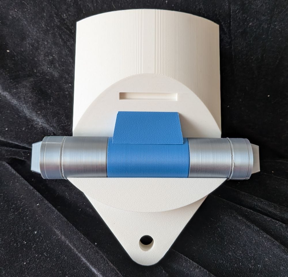
I then printed the remaining parts needed to attach the cylinders to the ankle. Once everything was cleaned up, I fitted the parts together and glued the assembly in place.
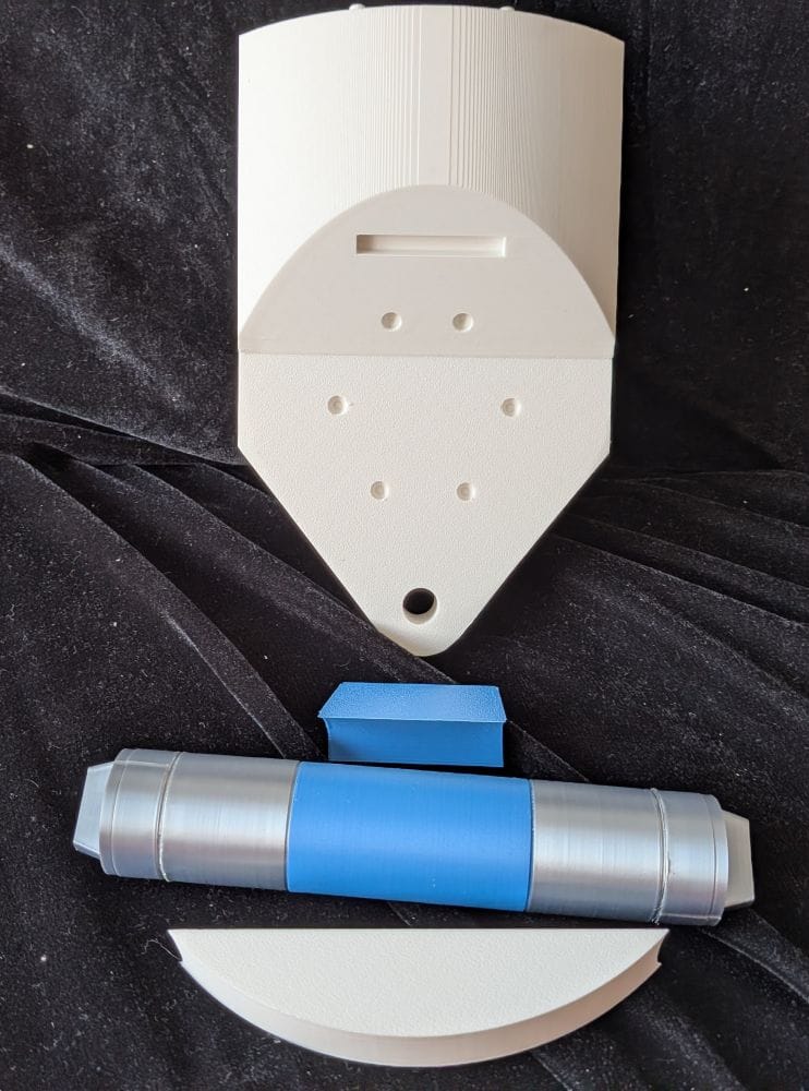
While I was waiting for the glue to set, I kept the other leg moving forward and printed the same set of parts for the right ankle. This meant I could make use of the curing time rather than having the printer sitting idle, and kept both legs progressing together.
The final part of the ankle assembly was the detail pieces on the side. These were designed to be printed in silver and blue, so I set the printer up to print both colours and, thankfully, the results came out really well.
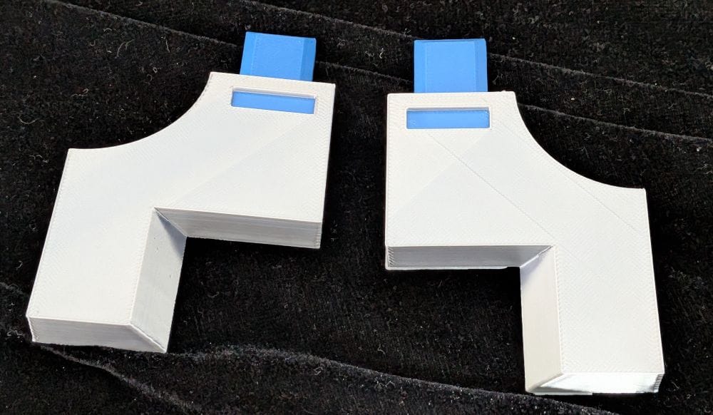
Gluing these pieces in place was a little more fiddly, though. Unlike some of the other parts, I couldn't use the filament pin holes to help with alignment, so I had to take a bit more care when positioning each piece. Once everything was lined up correctly, I glued the details into place and left them to set.
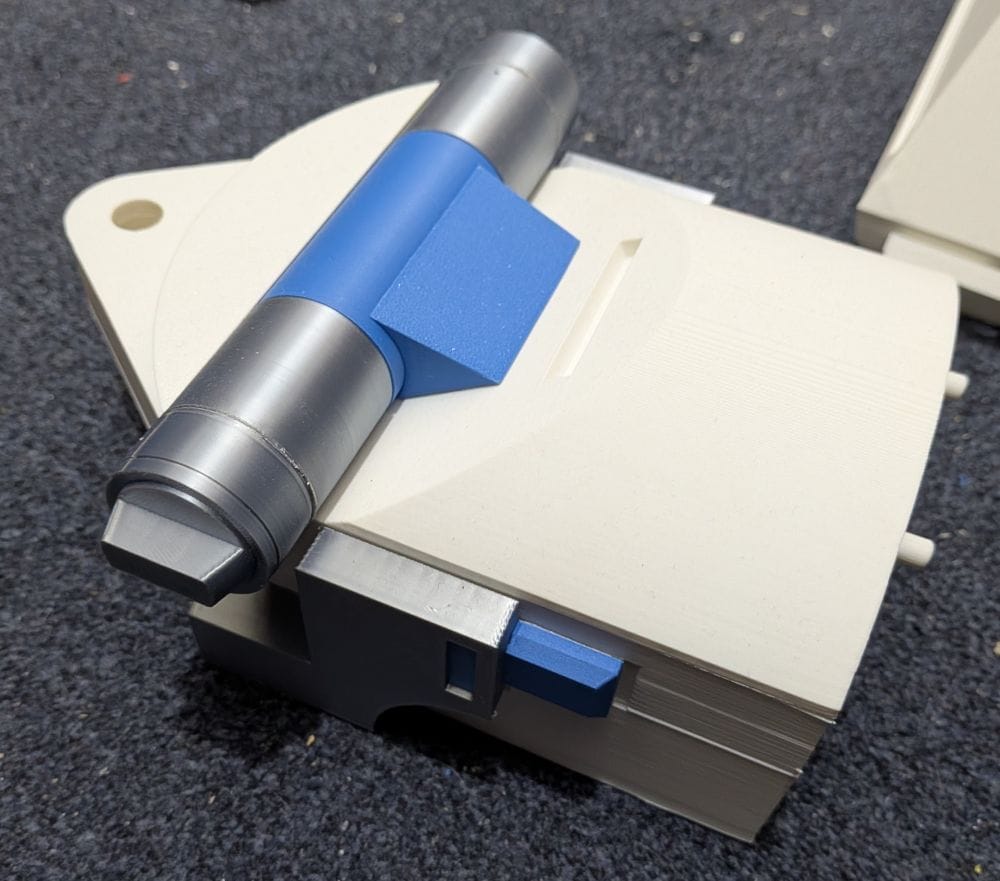
With both legs now printed, and before moving on to the greebles for the boosters and the other smaller parts, I decided to fit the magnets to the upper legs and horseshoe booster covers.
There are four holes in the upper leg for 10 x 5mm magnets, along with two more holes for the booster cover. It was a nice, simple job to do and didn't take very long.
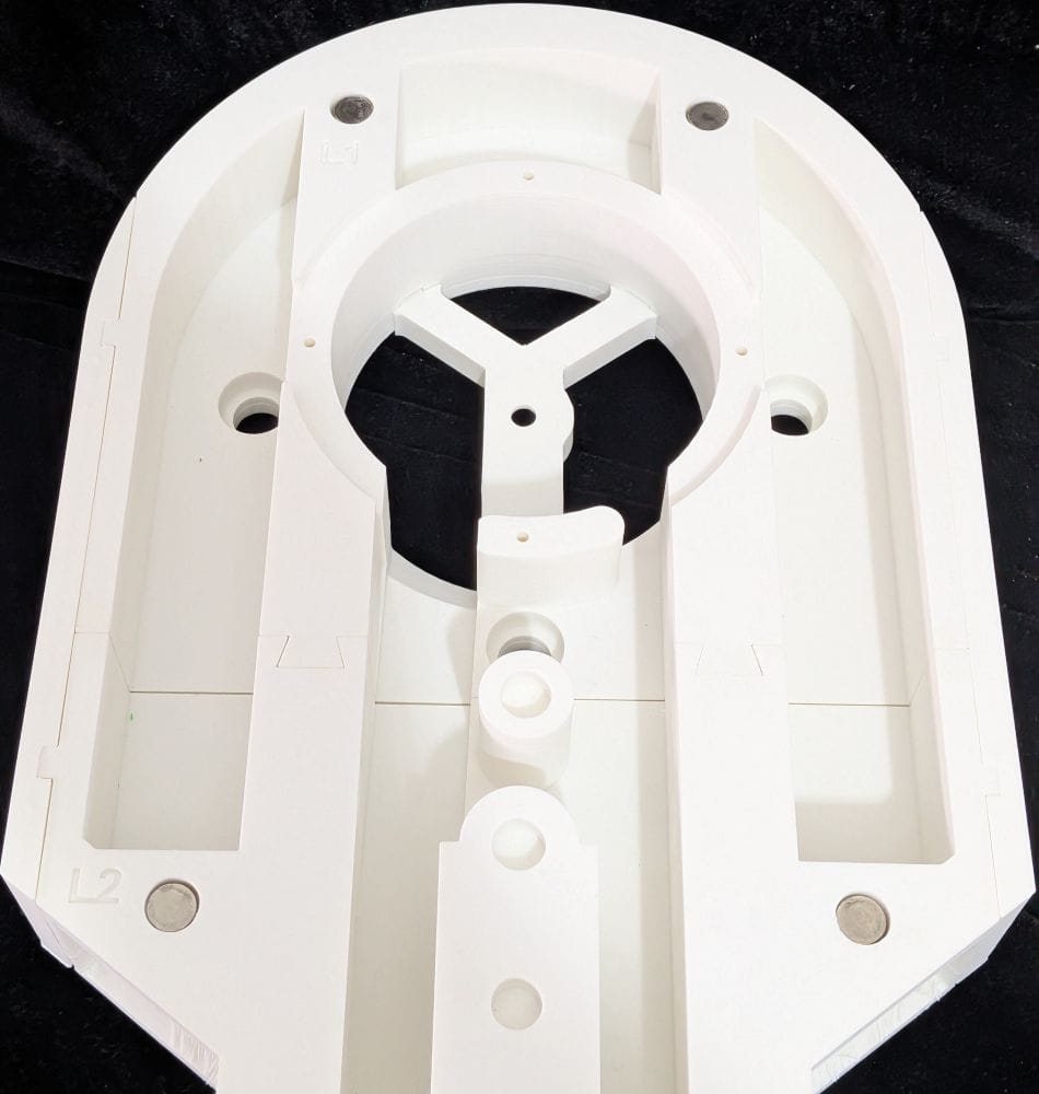
The main thing I had to be careful about was getting the polarity of the magnets the right way round. With magnets being rather unforgiving if you get that wrong, I made sure to double-check the orientation before gluing them in place. It would have been a bit of a disaster to get all the magnets fitted only to discover that I'd installed them the wrong way around!
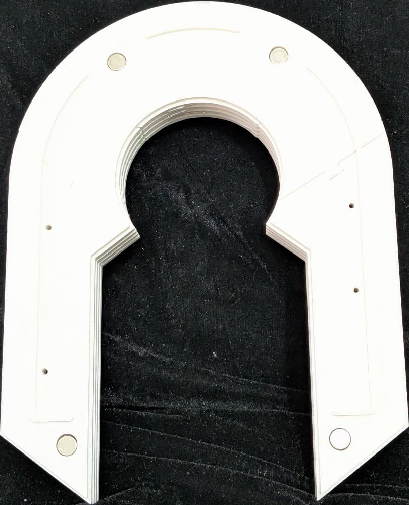
Thankfully, I took my time and checked the polarity at every stage, so everything worked out perfectly. There were no backwards magnets to discover later, which was a relief!
There's also something very satisfying about seeing the horseshoe cover simply clip onto the side of the leg and hold firmly in place. It's a small detail, but it makes the assembly feel much more finished and is a good example of how the magnets add some useful functionality without making the parts complicated.