
R2-D2 Part 13: Centre Leg
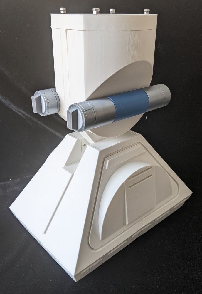
The centre leg is finally taking shape, with the centre foot, ankle, cylinders and 3D-printed omni wheels all coming together. There are a few printing challenges along the way, but the finished assembly is starting to look great.

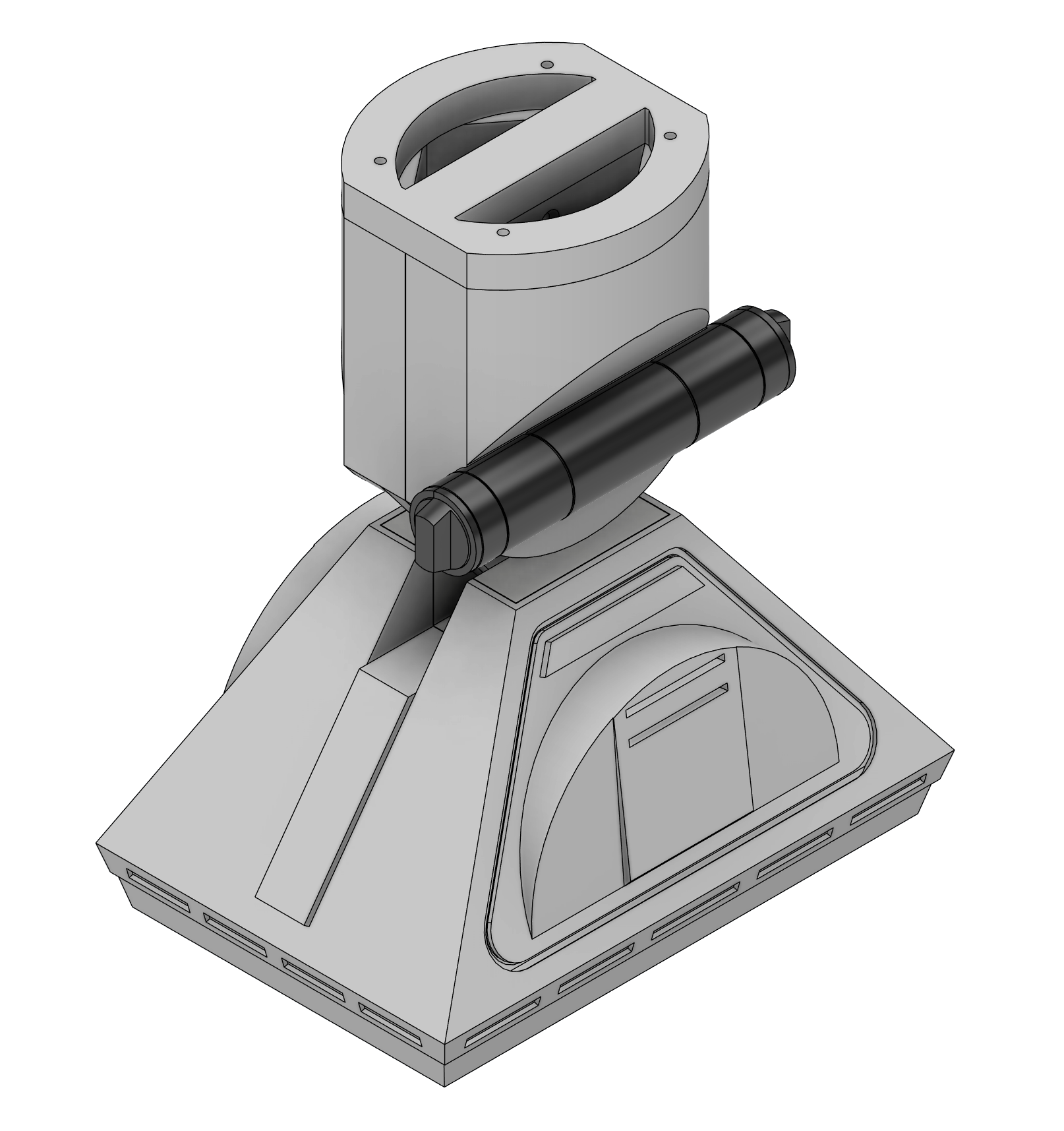
The first components I printed were the outer skins for the centre foot. This immediately presented a problem: the main foot skin was too large to fit on the build plate of my Bambu Lab A1. To make it printable, I had to split the skin into two halves. Even after dividing it, both pieces were still very large and required extremely long print times.
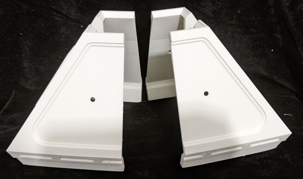
There was also a substantial overhang on the inside of the foot skin, so I decided to use supports rather than risk the print failing. I added further support around the outside, using PETG as the support interface so it could be removed more easily afterwards. As well as supporting the overhangs, I think this helped stabilise the parts on the build plate, which was especially useful given their size and the length of the prints.
After carefully reorienting each half to find the best position on the build plate, I started the prints and hoped for the best. Considering their size and duration, I was pleasantly surprised by how well they turned out. Both halves printed incredibly well, and the PETG interface made the supports relatively easy to remove.
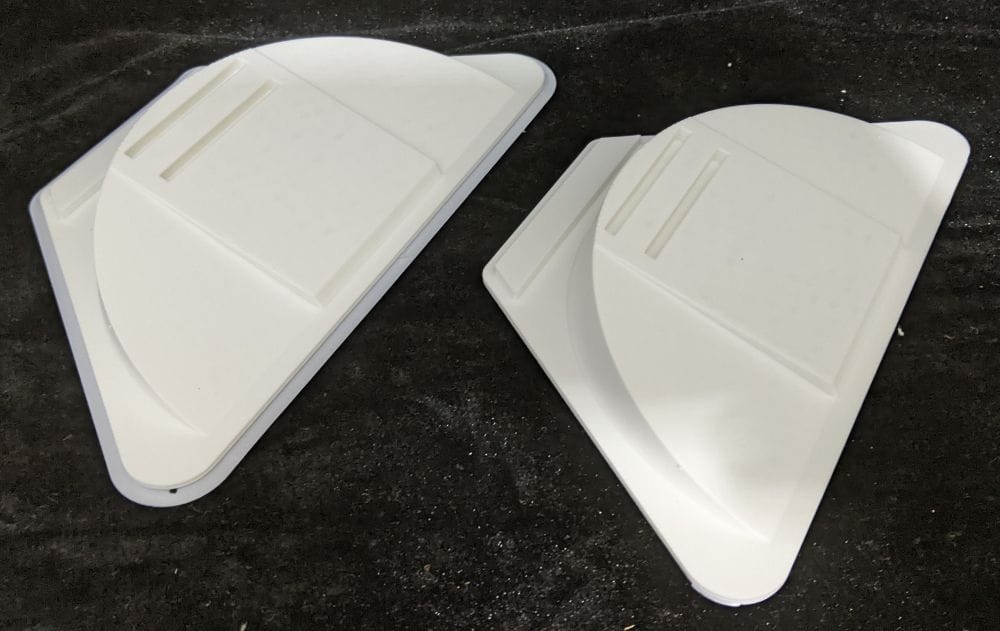
I then printed Side Skin A and Side Skin B. Both parts could be printed flat on the build plate, making them much more straightforward, and they came off the printer looking very good. With all four skin sections successfully printed, I had the beginnings of the centre foot ready for assembly.
After removing all the supports and brims, I gave each part a little clean-up to prepare the joining edges. Once everything was ready, I carefully aligned the four skin sections and glued the complete centre foot skin together.
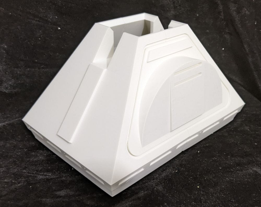
With the centre foot skin glued together, it looked very good overall. I did notice a small amount of curling along the bottom edge, but I don’t think it will be particularly noticeable once the centre foot is fully assembled.
My next print was the centre foot bracket, which is made up of three relatively square parts that could all be printed flat on the build plate. There were no problems with any of the prints, and when I offered the three pieces together, they fitted perfectly. With no adjustments required, I glued them together straight away.
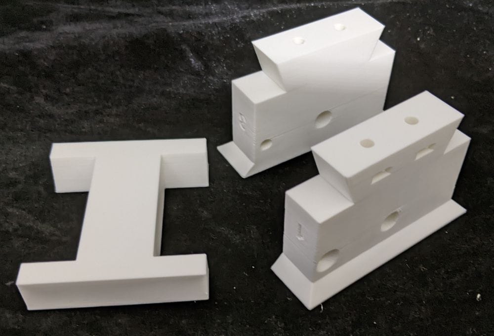
The completed bracket sits inside the top of the centre foot skin. It connects the outer foot assembly to the internal structure that will hold the wheels, as well as providing the mounting point for the main centre leg extending down from R2-D2’s body.
Once the glue had fully cured, the completed bracket was perfectly square and fitted neatly into the top of the centre foot skin.
The next parts I printed were Main Ankle A and Main Ankle B. When I first loaded Side A into the slicer, I noticed a large enclosed gap inside the model and wondered whether it would need supporting. However, the slicer indicated that it should print successfully without supports, so I decided to leave it as it was.
As the print progressed, I could see that it was bridging across a substantial internal space. Some of the other gaps in the model were clearly there to provide access to the screw holes, but I couldn’t work out the purpose of this particular cavity, as it was buried deep inside the part and contained no visible fixings.
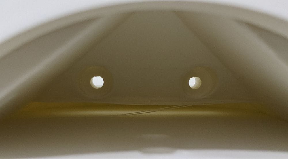
When Main Ankle A had finished printing, the unsupported area looked very messy inside. The outside of the part looked fine, but the ankle was no longer perfectly square and had developed a noticeable bow.
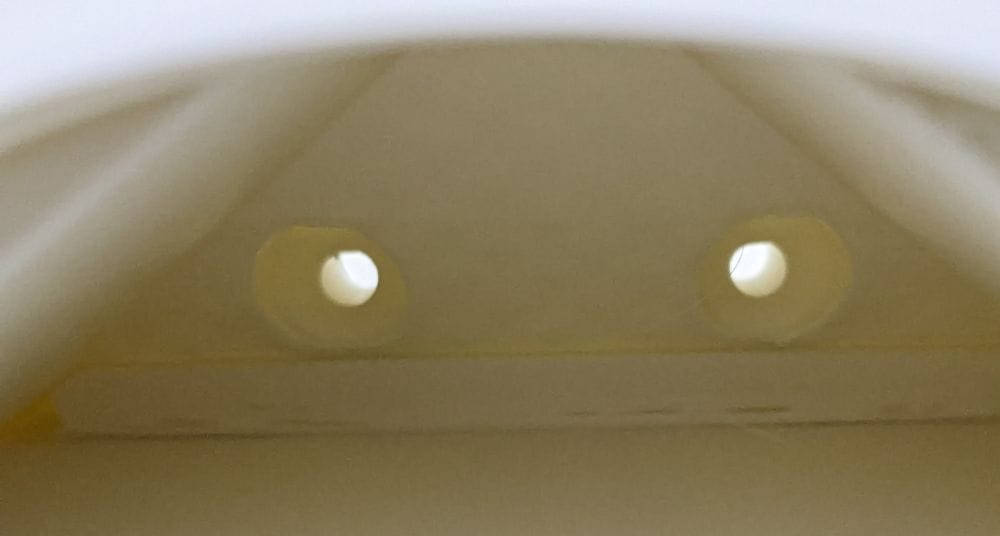
Because of this, I changed my approach for Main Ankle B and added supports inside that section. As I could see no reason why the internal gap needed to remain empty—and there would be no practical way to remove the supports afterwards—I decided to leave them permanently enclosed within the finished part.
When I finally offered the two main ankle parts together, I was gutted to discover that both of them had warped—something I hadn’t noticed when they first came off the printer. I considered reprinting it with a brim, as I hadn’t used one for the original print. However, given the size of the part and the length of time it took to print, I decided against starting again.
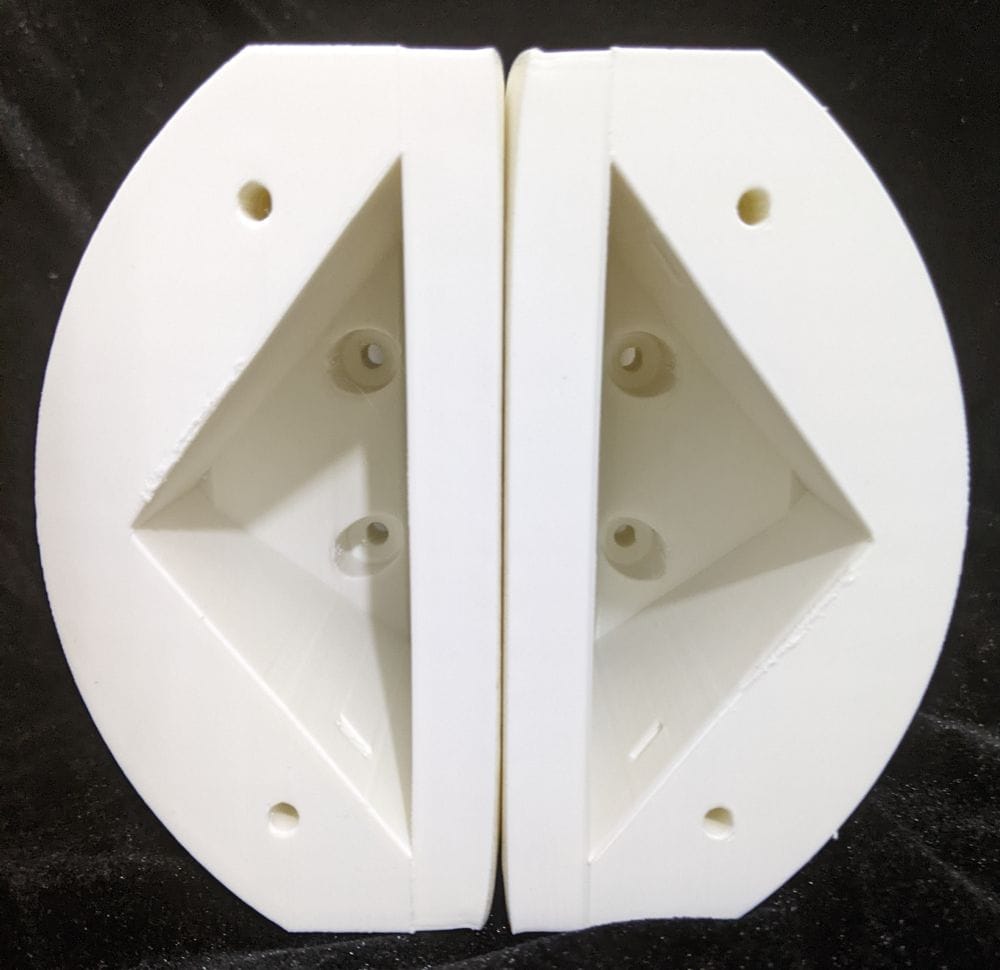
Instead, I chose to live with the warping, provided the two halves could still be joined securely. After carefully bringing them together, I found that they did fit well enough to be glued. The warp may leave a small visible gap, but if necessary, I can fill and smooth it later to create a more seamless finish.
With both the centre foot bracket and the two ankle halves now glued together, I decided to test-fit the joint using the 3D-printed pin. I wanted to make sure everything would connect properly without introducing any further problems.
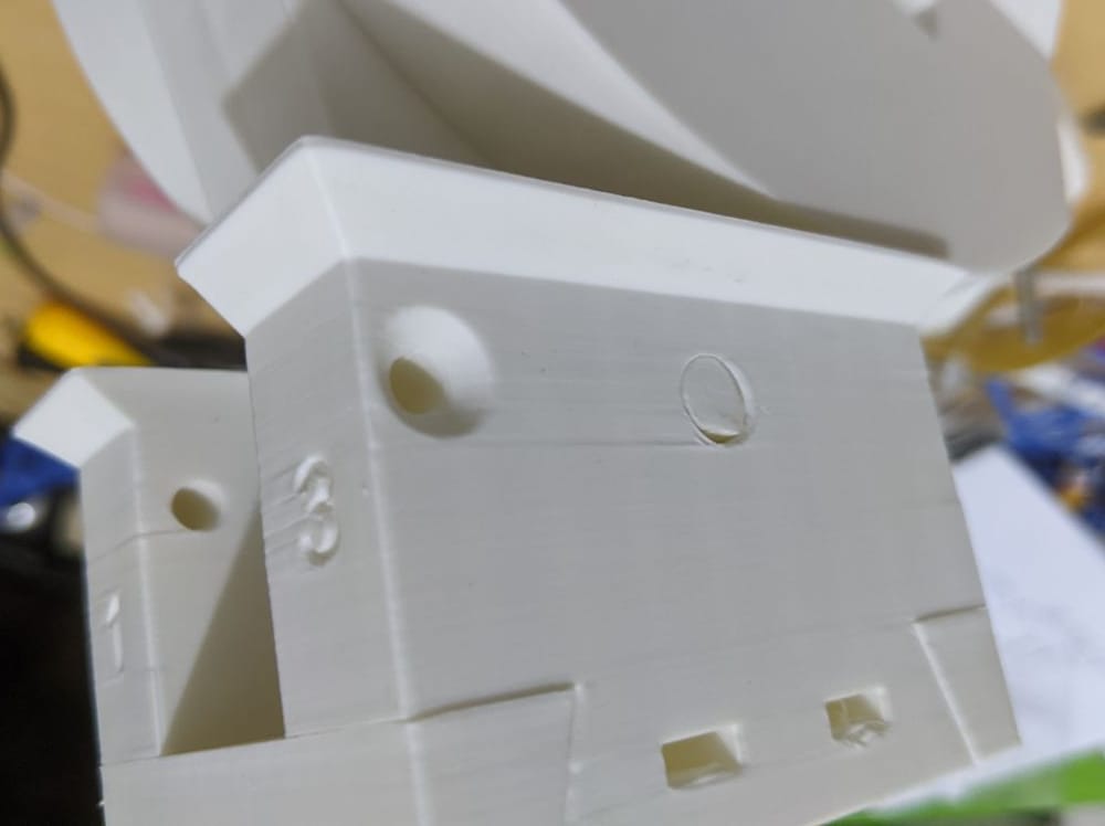
The pin was extremely tight in the ankle but remained loose inside the centre foot bracket, which was exactly what I needed. I carefully hammered the pin into the ankle until it was firmly seated. The fit was so secure that no glue was required.
With the centre foot bracket and main ankle connected, this section was almost complete. The only remaining pieces were the two cylinders fitted on either side of the ankle.
The standard cylinder design is relatively simple, consisting of two parts joined together. However, I found a modified five-part version that allowed me to print the outer sections in silver and the centre section in blue, matching the appearance of the original R2-D2 more closely.
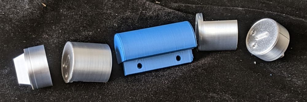
My main concern was how the five pieces would connect. The modified design used 3 mm × 10 mm pins, and although I initially considered printing them, I wasn’t sure how well my printer would handle something so small. I had previously printed bolts of a similar size, but they hadn’t turned out particularly well.
As I was already printing some other components in PETG, I decided to add the pins to the build plate and see what happened. To my surprise, they printed perfectly. I was equally pleased when I offered them up to the cylinder parts and found that they fitted perfectly as well.
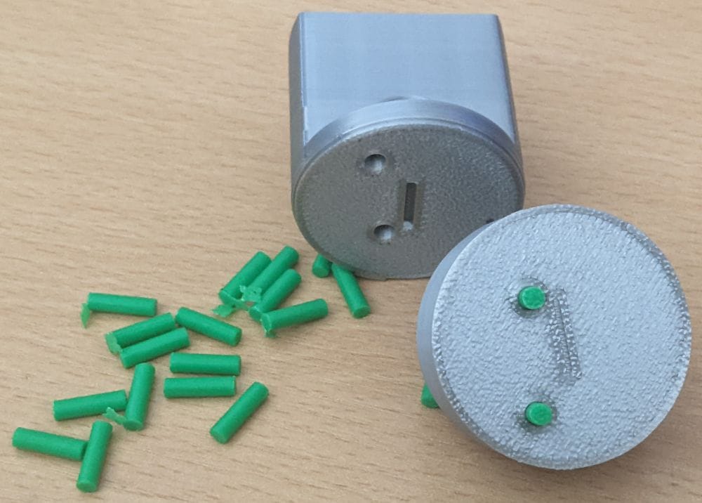
Once the cylinders were assembled and glued together, they looked fantastic. I have to admit that some of the printed edges weren’t perfect, but the combination of the silver outer sections and blue centre sections worked extremely well. Despite those minor imperfections, I was very happy with how they turned out. All that remained was to glue one cylinder to each side of the ankle.
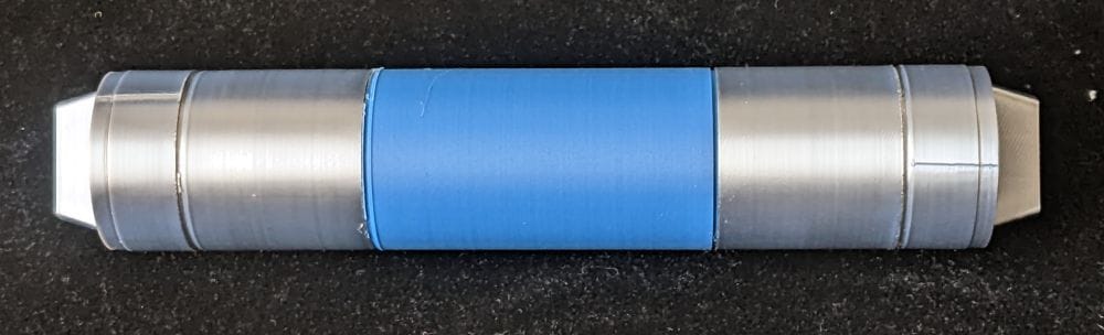
With the cylinders glued securely to either side of the ankle, this section of the centre leg was finally complete—and I think the finished assembly looks great.
The Omni Frame and Wheels
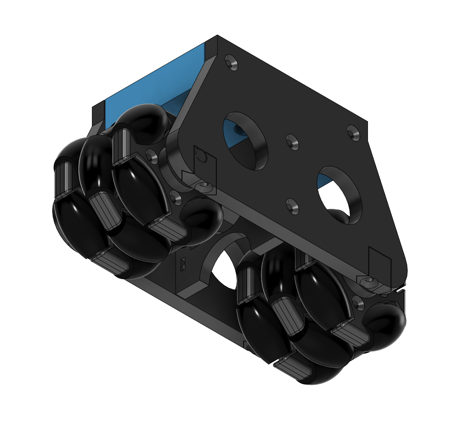
At this point, I was ready to call the centre leg complete and attach it to the main R2-D2 body. However, before doing so, I began thinking about the wheels.
As I’m not adding electronics or remote-control movement, the build doesn’t technically need them. Even so, I wanted to explore the possibility of fitting wheels to make the centre foot feel properly finished—and perhaps make the completed R2-D2 a little easier to move.
Looking at the omni-wheel frame, I found that it was made up of six relatively simple parts, with a couple of them duplicated. As each piece was completely flat, they could be placed directly on the build plate and should be straightforward to print.
The omni wheels themselves were a little more complicated. Each frame was made up of six parts that would eventually hold the small rollers around its outside edge. Each roller was then made from two separate pieces: a solid core and a flexible tyre. Altogether, I would need to produce 24 of these two-part rollers.
I could have bought ready-made omni wheels online that would fit inside the frame, but where would be the fun in that? If the parts could be 3D printed, I might as well try making the complete wheels myself.
For my first test print, I decided to produce one of the frame sections along with four rollers. The frame required support inside its hub, which was simple enough to add using PETG as the support interface. This allowed the supports to be removed easily and left the inside of the hub relatively clean.
The rollers presented a different problem because I didn’t have any flexible filament for the tyres. Instead, I decided to combine each solid core and tyre into a single rigid part. By positioning both models centrally in exactly the same place on the build plate, the core and tyre overlapped and merged in the slicer, allowing each roller to be printed as one complete piece.
Work in Progress
All I needed to complete this first frame were four lengths of 3 mm steel rod. I initially looked online to see whether I could buy some cheaply, but then realised that an ordinary steel coat hanger would be ideal for the job.
Unfortunately, I didn’t have one available. Until I could get hold of a suitable coat hanger and cut the four pins to length, I couldn’t continue assembling the omni wheels.
While I waited to find some suitable steel rod, I moved on to printing the main omni-wheel frame. I didn’t want to use up any more of my white filament on parts that would largely be hidden, so I used some of the green PETG I normally kept for support interfaces instead.
I printed all eight required parts in PETG, including the axles for the wheels. Although the green colour was not particularly accurate, these components would be inside the centre foot, so I didn’t think it would matter. To my surprise, every part—including the axles—printed perfectly.
Another option would be to print the rollers in black, even if I continued using standard PLA rather than flexible filament. Before permanently assembling the omni wheels, I may print a couple of black test rollers and compare them with the white ones. That should give me a better idea of which colour looks best beneath the finished centre foot.