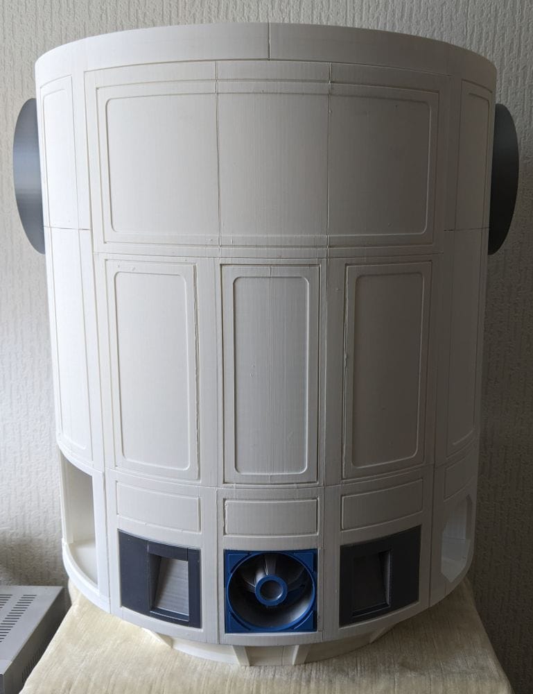
R2-D2 Part 11: Rear Panel
Building the removable rear panel for my full-size 3D printed R2-D2, including greebles, magnetic access hatch, locking mechanism, alignment challenges, and a few printing mistakes that were solved along the way.

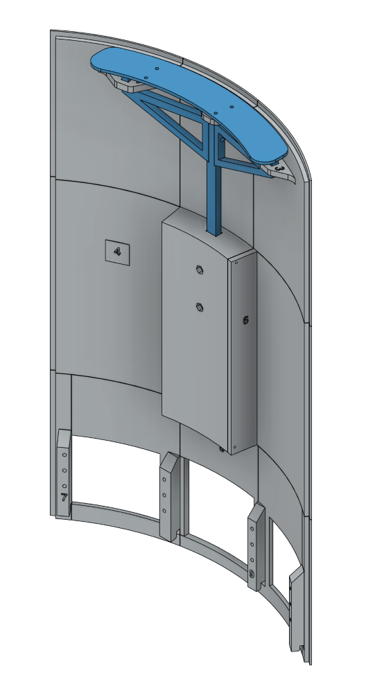
The rear removable panel is made up of 16 printed parts, with nine of those forming the main panel itself. At first glance it doesn't look like a particularly complicated section, but there are quite a few smaller components that need to come together before it's complete.
Parts 7, 8 and 9 are each made up of multiple pieces and are a little more fiddly than the rest of the panel. These sections form the openings for the rear greebles, so getting everything lined up accurately will be important to ensure the finished panel looks right.
The remaining parts make up the mounting hardware, including the brackets and locking levers that allow the rear panel to be removed and secured back into place. Once those are assembled, the final job will be fitting the rear greebles themselves, bringing one of the most recognisable details of the back of the R2-D2 body to life.
I decided to start by printing panels 1, 2 and 3, as these contain the bracket holes for the locking levers that secure the rear panel in place. Like many of the previous body sections, they also include filament locating holes for alignment. Looking at how these parts fit together, I had a feeling those locating pins would be more important than ever, helping to keep everything square and properly aligned before any glue was applied.
The first three parts were printed with a brim to give them a little extra stability during the print. As they are quite tall and relatively thin, I was expecting there to be a risk of them lifting or wobbling, but they all printed exceptionally well. At this stage, there were no noticeable issues at all, giving me a good start to the rear panel assembly.
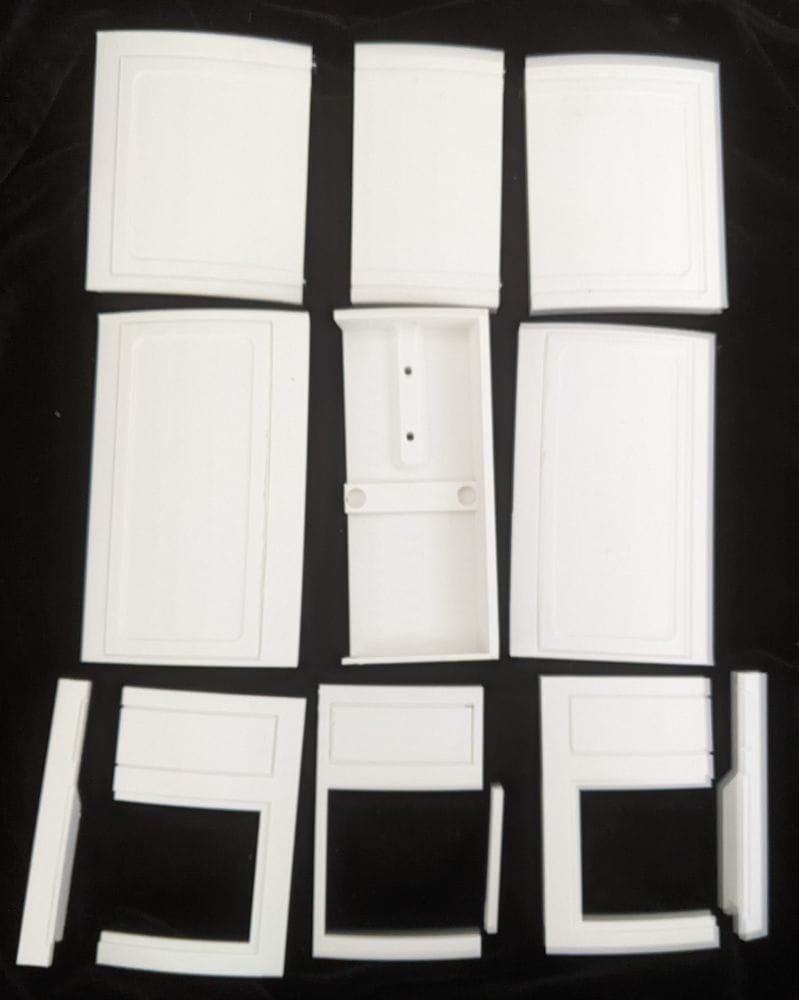
The remaining panel sections also printed without any problems until I reached Panel 8. This section is made up of two separate parts, and both had a slight amount of warping, leaving them just a little out of alignment. Fortunately, it wasn't severe, and I was confident it could be corrected during the assembly process without needing to reprint the parts.
When it came to gluing the lower three panels together, I found the job a little more difficult than I had expected. Even though the parts included holes for filament locating pins, it still took a fair amount of adjustment to get everything lined up before applying the glue.
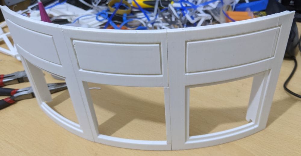
Once the glue had cured, I noticed that one of the parts was slightly out of alignment by around half a millimetre. It's not particularly noticeable on its own, but I was a little concerned that such a small error could become more significant when it came to fitting the next layer of panels on top. At this stage, all I could do was continue with the build and hope the slight misalignment wouldn't cause any problems later on.
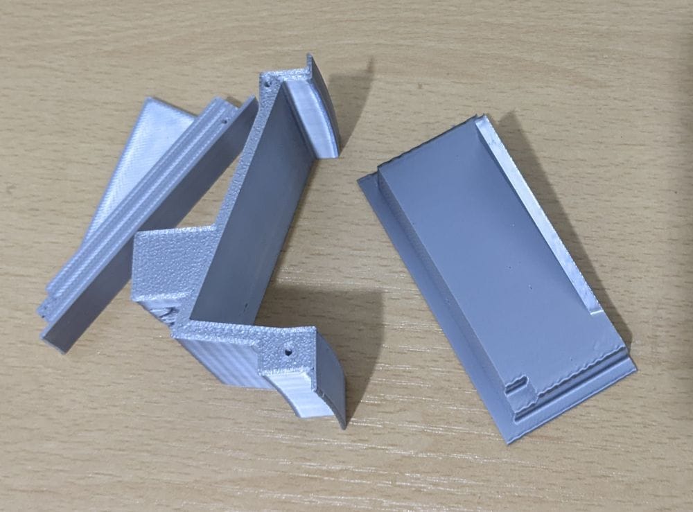
The coin return slots, printed in silver, were handed left and right, with each one made up of three separate parts. Thankfully, they were straightforward to assemble, and after a quick clean-up they went together without any problems. Once glued, they looked the part and added another distinctive detail to the lower section of the rear panel.
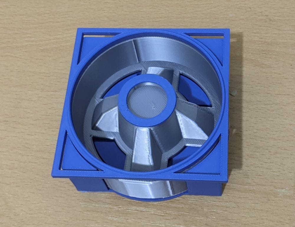
The rear power coupling was a little more straightforward, with a combination of silver and blue parts. Unfortunately, this is where I made a small mistake. I printed the outer ring in blue when it should actually have been silver. To make matters worse, I didn't notice the error until everything had already been glued together. It's only a minor detail, though, and unless someone is studying the rear panel closely, I don't think it's something that will stand out too much.
Behind the lower three panels sits a mounting bracket that holds all three greebles securely in place. The design allows the bracket to be either screwed or glued into position. As I have no plans to remove these parts in the future, I decided to glue the bracket in place. It simplified the assembly and gave the greebles a solid, secure mounting without the need for additional hardware.
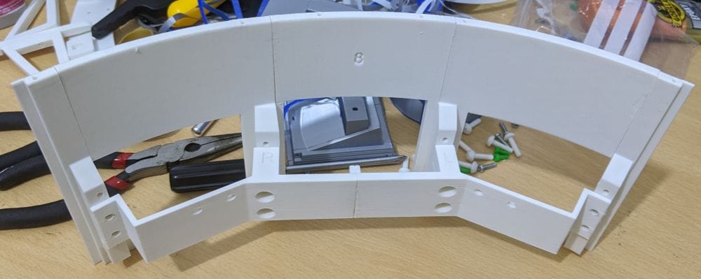
I did briefly experiment with 3D printing the screws that are intended to secure the bracket. You can actually see a few of my attempts sitting in the background of this photo. Unfortunately, they just weren't strong enough or accurate enough to work properly. Rather than waste more time trying to get them right, I decided to glue the bracket into place instead. Given that I have no intention of removing the greebles in the future, it seemed like the simplest and most reliable solution.
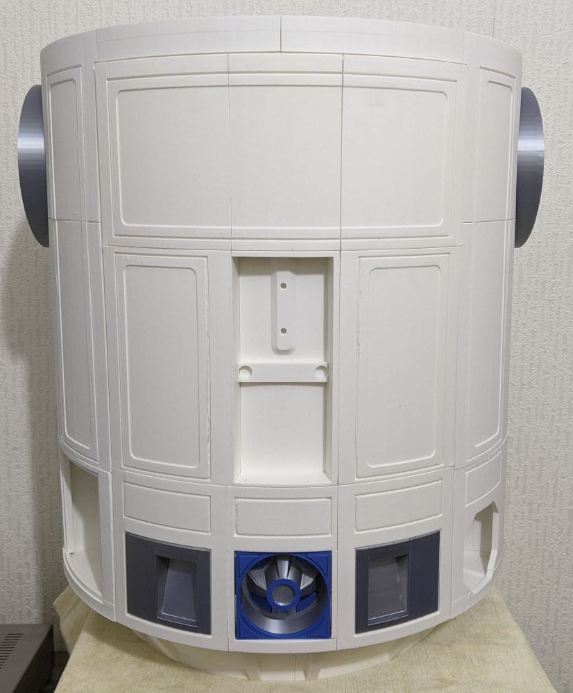
With the lower three panels now glued together, I offered them up to the main R2-D2 body for a test fit. Overall, I was really pleased with how they looked. The only things that stood out were the slight misalignment between the panels, which I'd already noticed during assembly, and my colour mistake on the rear power coupling. Thankfully, neither issue is particularly obvious unless you're looking for them, and once the rest of the rear panel is assembled, I suspect they'll blend into the finished build quite well.
When it came to assembling the remaining panels, my original plan was to glue the middle three together first, then the top three, and finally join all three sections into one complete rear panel. However, after looking more closely at how everything fitted together, I realised the curve of the panel had to be quite precise if it was going to sit correctly against the back of the R2-D2 body.
Before committing to any glue, I decided to do a complete dry fit. To my surprise, the filament locating pins fitted into several of the panels perfectly. They pulled the parts together tightly and created a surprisingly rigid assembly, making it much easier to see how the finished panel would look.
Looking at the dry-fitted panel, I had another idea. Rather than gluing each section together separately, I decided to leave the entire assembly held together by the locating pins and use the glue almost like a weld from the inside. By running beads of glue along the internal joints, I was hoping it would wick into the seams, bonding the parts together while allowing the locating pins to keep everything perfectly aligned. It seemed like a much simpler approach and, hopefully, one that would preserve the correct curve across the whole panel.
When it came time to glue the rear panel together, the method I had planned worked remarkably well. Rather than dismantling the whole assembly, I simply pulled each joint apart by a millimetre or so, applied a small dab of glue, and then pressed it back together before moving on to the next section. Working my way around the panel like this allowed the locating pins to keep everything aligned, while the glue bonded each joint from the inside. It was a surprisingly quick process, and before long the entire rear panel had been assembled into one solid piece.
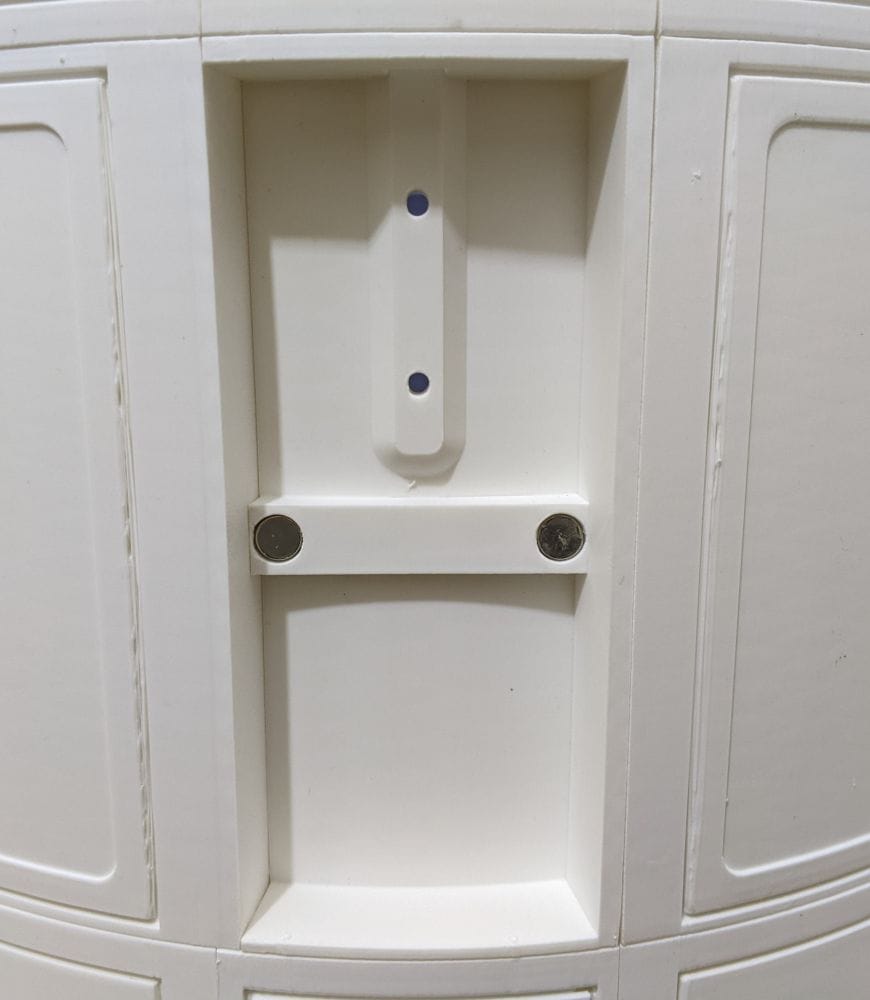
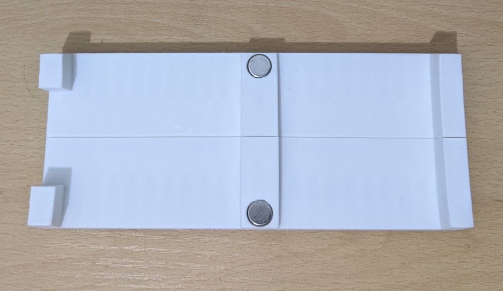
With the main panel complete, I turned my attention to the small access panel for the locking mechanism. This uses 10 × 5 mm magnets to hold it securely in place while still allowing it to be removed whenever access to the locking levers is needed. Installing the magnets was straightforward, but as always, I made sure to double-check the polarity before gluing them in place—it's much easier to spend a few extra seconds testing them than to discover one has been installed the wrong way round after the glue has cured.
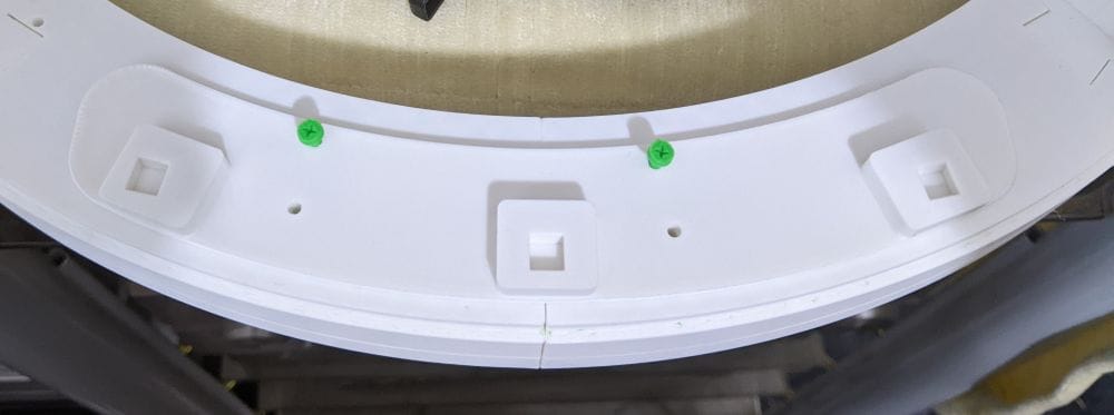
Next, I glued the locating lugs into the top of the rear opening on the main body. These provide the locating points for the rear panel when it's fitted, so getting them in the correct position was important. To hold them in place while the glue cured, I improvised by using a couple of my failed 3D-printed screws as temporary spacers. They might not have been any good as screws, but they turned out to be the perfect size for keeping the lugs aligned, so at least those failed prints ended up proving useful after all.
When it came to printing the locking pins themselves, things didn't go quite so smoothly. All three parts failed fairly spectacularly. I'd printed them without a brim, and because of their shape, the corners lifted from the build plate, leaving each part with noticeable warping. They probably would have still functioned, but they looked far too untidy.
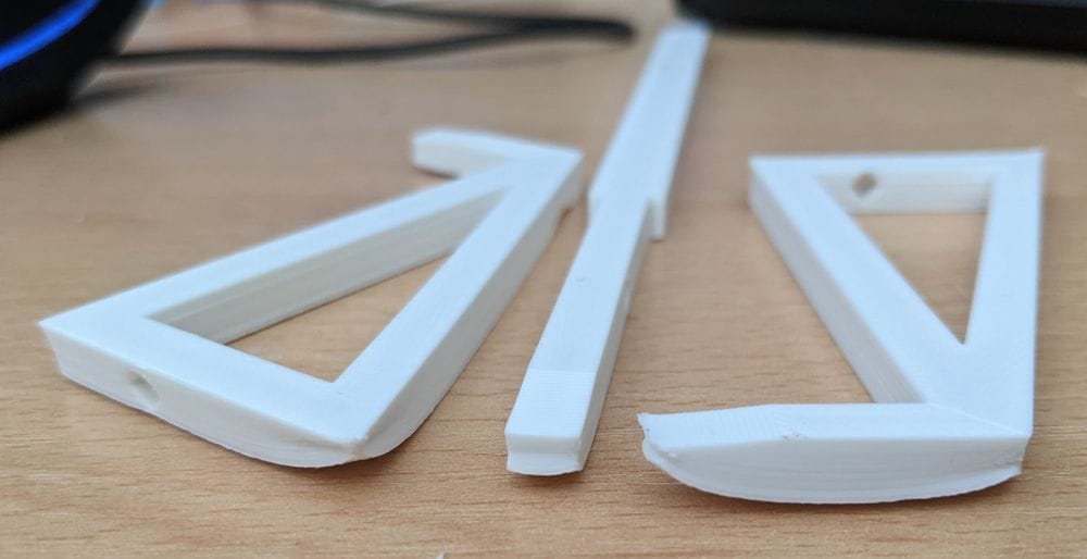
Rather than trying to make do, I reprinted all three parts with a brim. That simple change kept the corners firmly attached to the build plate throughout the print, and the replacements came out perfectly flat and square. After removing the brim and giving them a quick test fit, everything fitted perfectly, making them much better suited for the finished assembly.
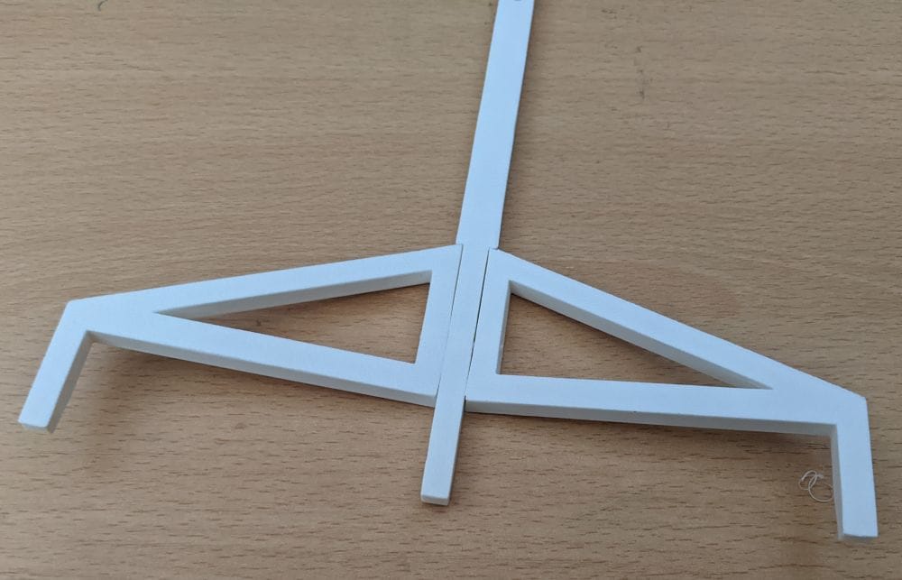
With the locking pins printed successfully, I assembled the locking mechanism on the inside of the rear panel. The holes that the locking bars slide through were a little tight, but that was easily fixed with a quick clean-up using a sharp craft knife. Once everything moved freely, I gave the mechanism a quick test by locking and unlocking it.
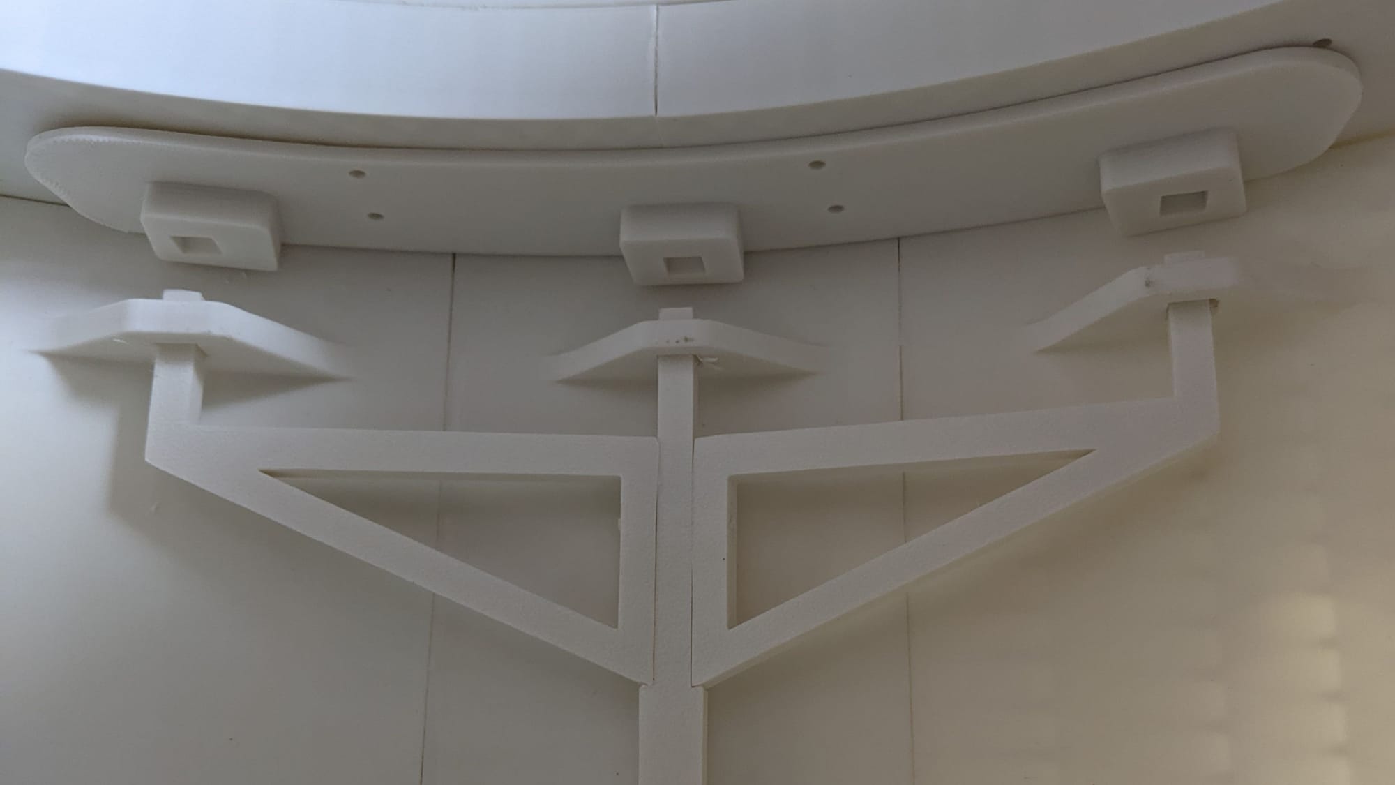
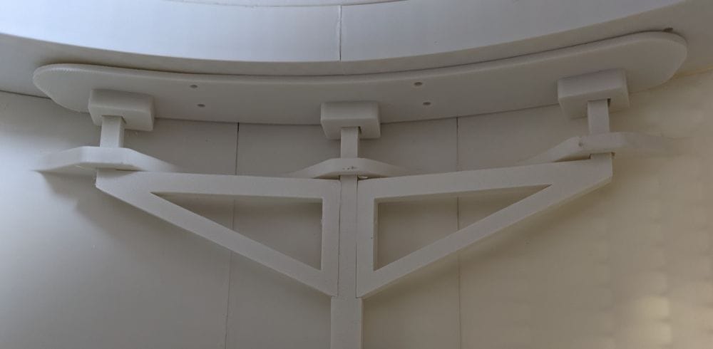
To my delight, it worked perfectly on the very first attempt. After all the measuring, printing and careful assembly, it was really satisfying to see the mechanism operate exactly as intended.
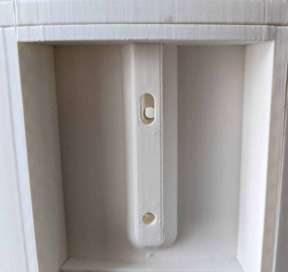
The only thing left to do was fit a couple of 4 mm nuts and bolts to secure the locking mechanism permanently in place.
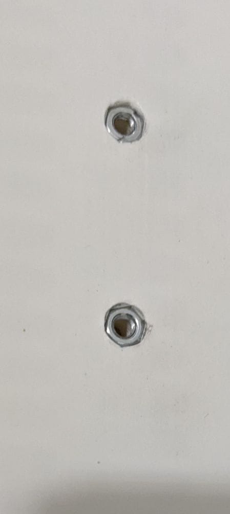
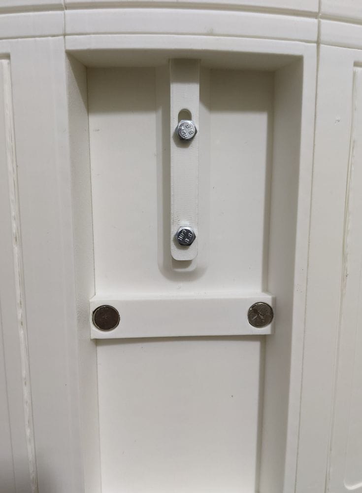
With those installed, I fitted the rear panel onto the R2-D2 body, engaged the locks, and finally attached the magnetic access hatch over the mechanism.