
R2-D2 Part 3: Ring 2
Ring 2 of my full-size R2-D2 build brought warped parts, filament jams, hinge assemblies, missing files, and careful gluing — but after plenty of problem-solving, the body section finally came together almost perfectly.
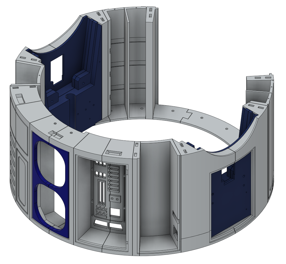
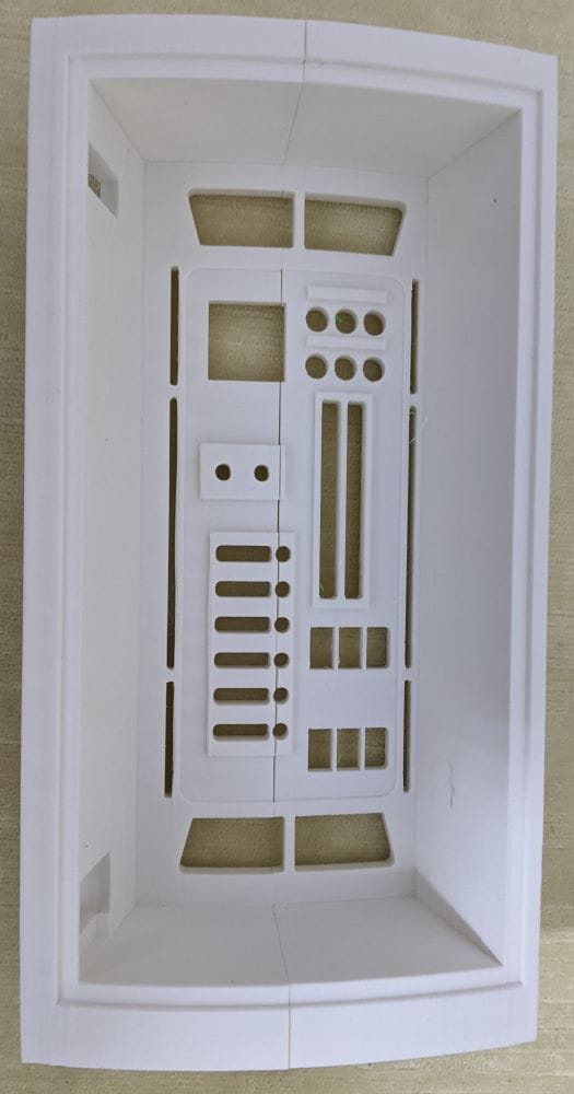
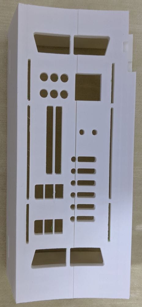
Ring 2 is made up of 21 sections, but in total it comes to 31 individual parts. Most of the sections print flat on the bed, although a few need a fair amount of support because of the added detail.
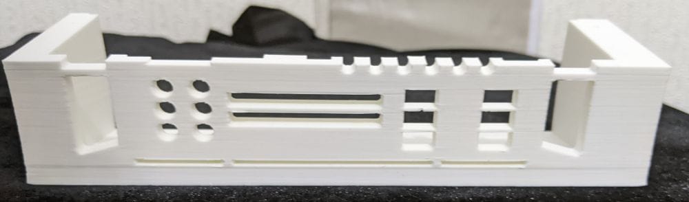
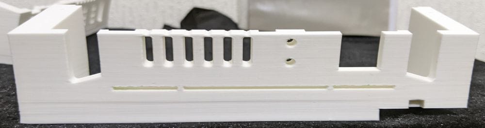
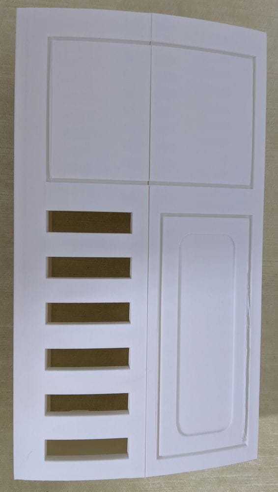
MB-Ring 2-1 looked like it might need supports, as it has six slot openings, but it actually printed without any issues. The same was true for MB-Ring 2-2, MB-Ring 2-3, and MB-Ring 2-4, which all printed cleanly without needing supports.
MB-Ring 2-5 was a bit more involved, with lots of slots and holes, so I decided to use supports with a PETG interface, as before. The print itself came out well, but the supports were a bit of a pain to remove. That said, taking it slowly paid off — and thanks to PETG not bonding to PLA, I was able to get them off cleanly in the end.
MB-Ring 2-6 was very similar to MB-Ring 2-5, as the two parts join together to create one larger section. I used the same approach again, with supports and a PETG interface.
This time, though, removing the supports was noticeably easier. Whether that was down to better settings, or simply getting more used to the process, I’m not sure — but it definitely made the clean-up quicker and less fiddly.
I later realised there’s an updated and revised version of these two parts that’s designed to be easier to print as a single piece, with slightly different holes and slots. I didn’t spot that at the time, but it’s good to know the option is there as a fallback. If I run into any issues when assembling the ring, I can always go back and print the revised versions instead.
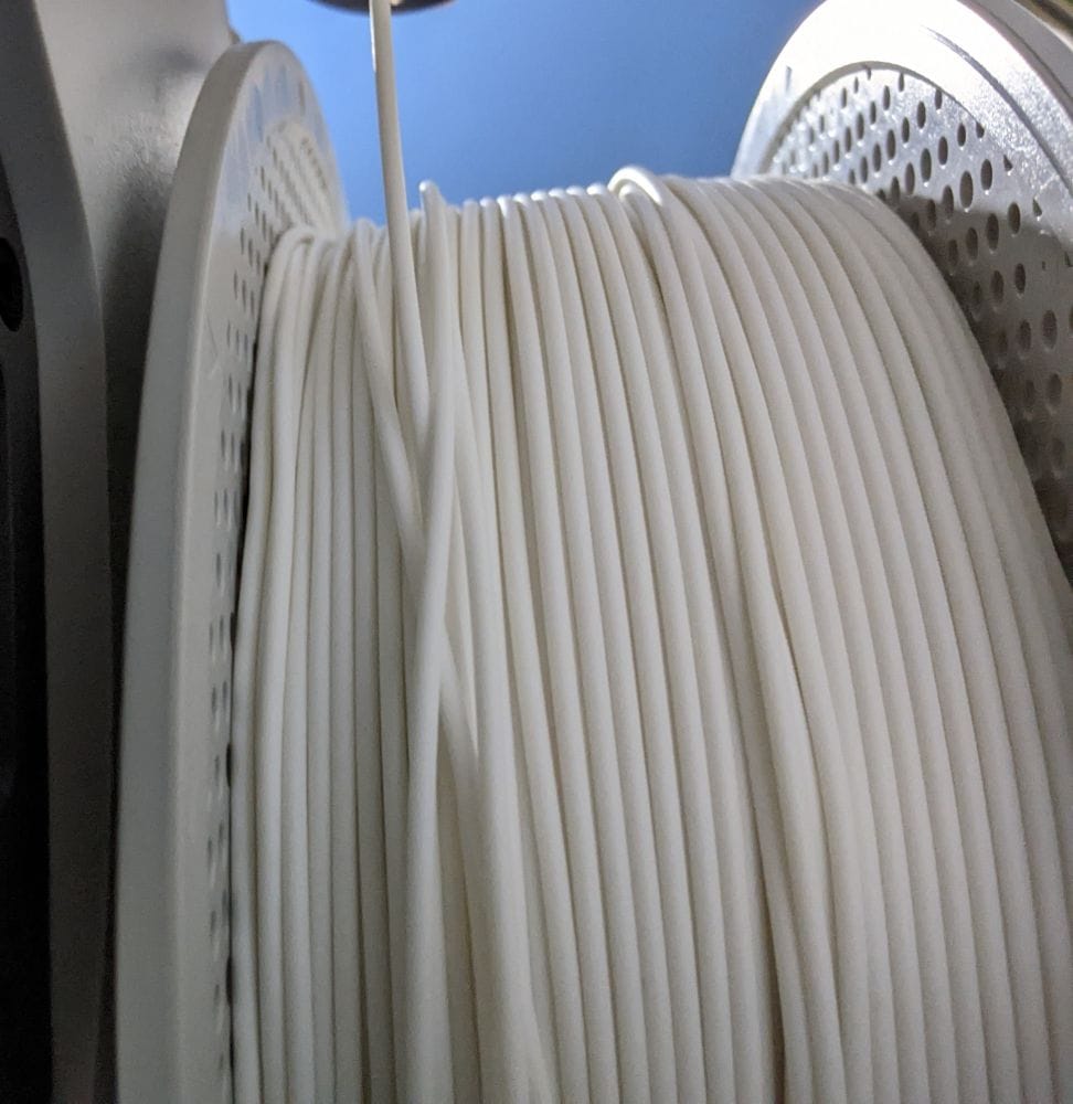
Parts MB-Ring 2-7 and MB-Ring 2-8 both printed well overall. I did run into a small issue on MB-Ring 2-8 when the filament ran out mid-print. The auto-refill system on the Bambu Lab A1 didn’t feed the new filament properly, which caused the print to stop.
Once I got that sorted, though, everything carried on fine and the part completed without any further problems.
However, on the next two parts — MB-Ring 2-9 and MB-Ring 2-10 — that’s where the real problems started.
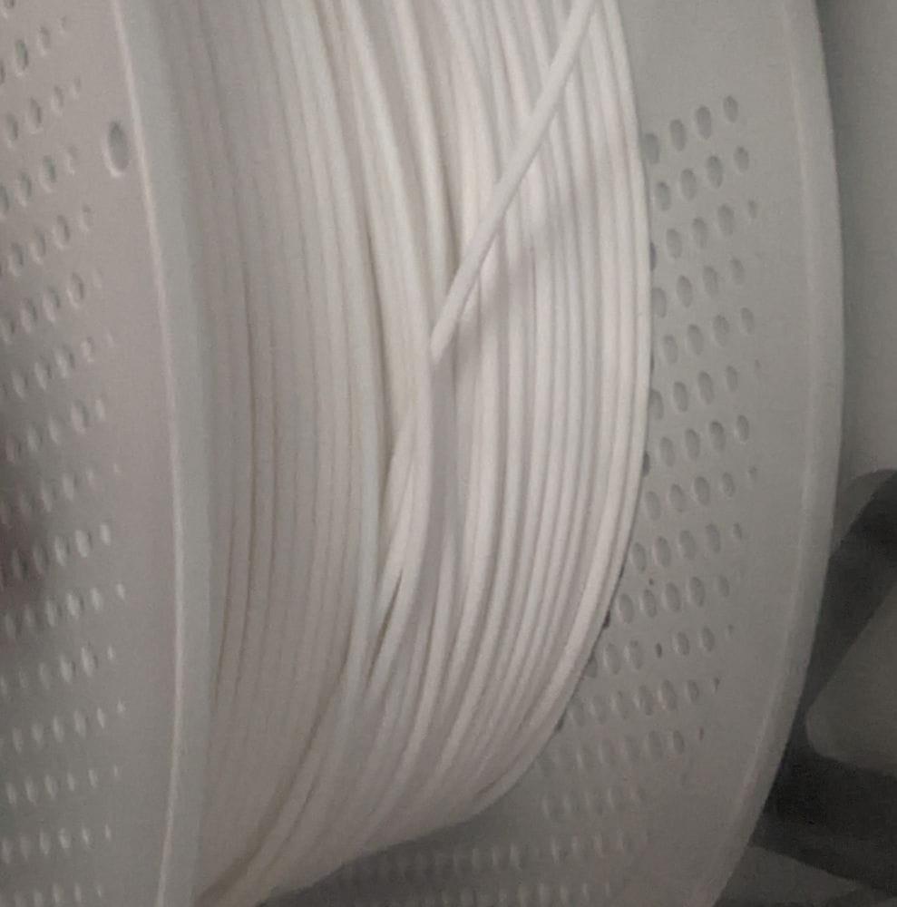
MB-Ring 2-9 is a fairly large piece and looks like it would need supports, but it actually doesn’t. I started the print, which was estimated to take around 2 hours and 50 minutes, and after about 40 minutes I went to check on it and found it had stopped because of a filament jam.
I cleared the jam and got the print going again, but not long afterwards it jammed again. The same thing kept happening — clear the jam, restart the print, then watch it jam again shortly after.
In the end, I spent over an hour effectively babysitting the printer, keeping a close eye on the filament spool just to keep the print running.
After the print finished, I removed the spool to check the filament. I then put it back onto the AMS Lite in a different slot and started MB-Ring 2-10 — another long print at around 2 hours and 33 minutes, and effectively the opposite half of MB-Ring 2-9.
It started off printing well, so at first I thought I’d solved the issue. But before long, the same problem returned, and once again I ended up babysitting the printer just to keep the print running.
At that point, I was convinced it had to be a bad spool. Once the print finally finished, I removed the filament again and cut away a good couple of metres from the spool. Sure enough, I eventually found the problem — the filament had become knotted on the spool.
After removing the knotted section, I put the spool back on and started printing MB-Ring 2-9a, MB-Ring 2-9b, and MB-Ring 2-9c. Each of these was another print of over two hours.
This time, though, everything worked perfectly. All three parts printed without a single issue — no jams, no interruptions, just smooth printing from start to finish. After the problems with MB-Ring 2-9 and MB-Ring 2-10, it was a relief to finally confirm that the filament spool had been the cause of the trouble all along.
Printing went smoothly from this point on. MB-Ring 2-11a, MB-Ring 2-11b, and MB-Ring 2-12 all printed well without any problems.
Parts MB-Ring 2-13, MB-Ring 2-14, and MB-Ring 2-15 were smaller, flat pieces, so I printed them together in a single run to save a bit of time.
MB-Ring 2-16, MB-Ring 2-17a, and MB-Ring 2-17b also printed cleanly with no issues.
The next larger parts — MB-Ring 2-18, MB-Ring 2-19, MB-Ring 2-18b, and MB-Ring 2-18c — were similar in size and shape to the earlier pieces that gave me trouble when the filament spool was knotted. Thankfully, after sorting out the filament issue, these all printed perfectly without any interruptions.
MB-Ring 2-20 and MB-Ring 2-21 also came out well, along with the MB-Ring 2-P plates, which are used to strengthen some of the larger sections.
Finally, I printed the MB-Ring 2 connectors, which are used to help align and strengthen the joins during assembly, along with the DataDoorArm assembly. The DataDoorArm is made up of three separate parts and needs to be fitted before the ring itself is glued together.
Gluing Ring 2
To start gluing Ring 2, I used the same tack-and-dab method as before, applying glue only to the inside of the joins to keep the outer surface as clean as possible. I began with MB-Ring 2-1 and MB-Ring 2-2.
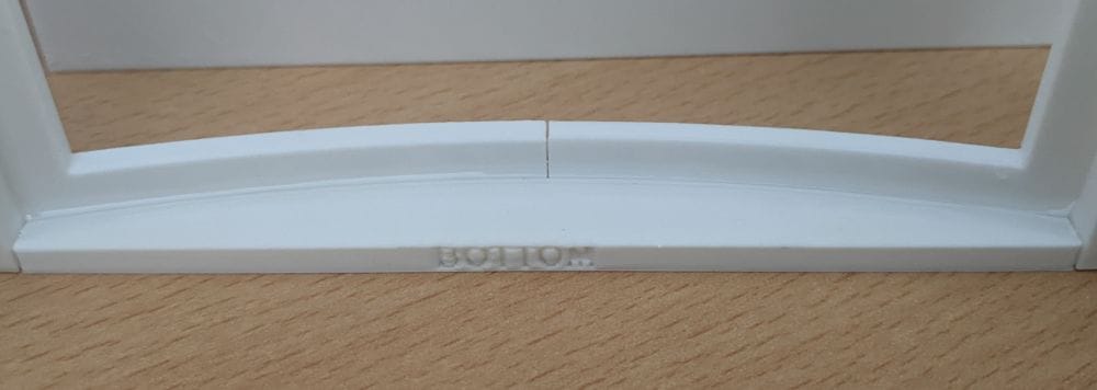
Parts MB-Ring 2-3 and MB-Ring 2-4 I assembled slightly differently. First, I carefully lined them up and applied a strip of glue to the inside at the bottom of the join. After holding it for a few seconds to let it grab, I repeated the process at the top, which helped keep the alignment steady while the rest of the joint set in place.
Parts MB-Ring 2-5 and MB-Ring 2-6 were assembled using the same process. Once the parts were aligned and tacked into place, I ran a line of glue down the centre join and held the pieces tightly together until the glue had fully set.
These parts joined well overall, but the seam lines are still fairly noticeable, so they’ll need a bit of filling and clean-up later on.
The next few parts will need a bit more careful planning before I start gluing them together, as some of the sections are surprisingly fragile until they’re fully assembled and reinforced.
I found that out the hard way during a test fit when I accidentally dropped MB-Ring 2-9 onto the carpet and it snapped. It wasn’t even a hard fall, but the shape of the part makes it fairly delicate on its own before everything is joined together.
That meant another reprint — and with MB-Ring 2-9 taking around 2 hours and 50 minutes to print, it was a frustrating mistake to make.
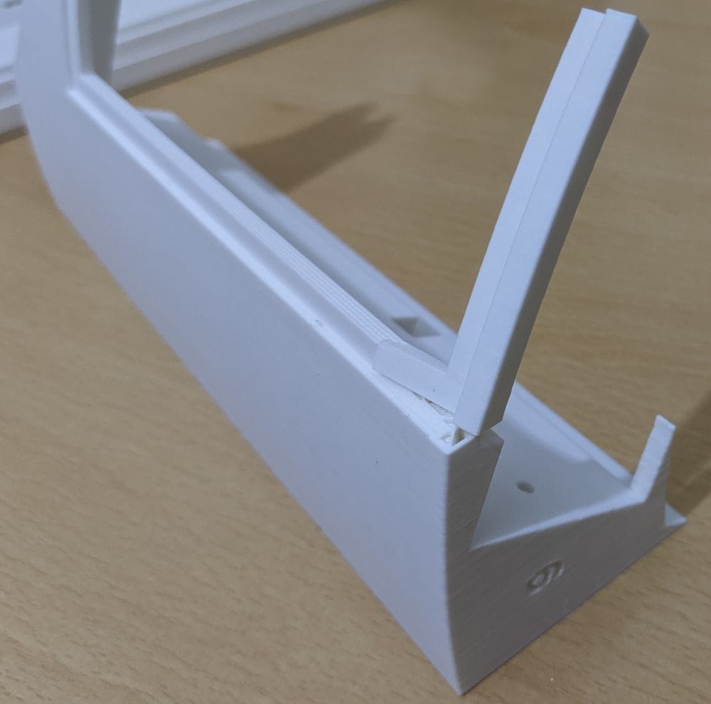
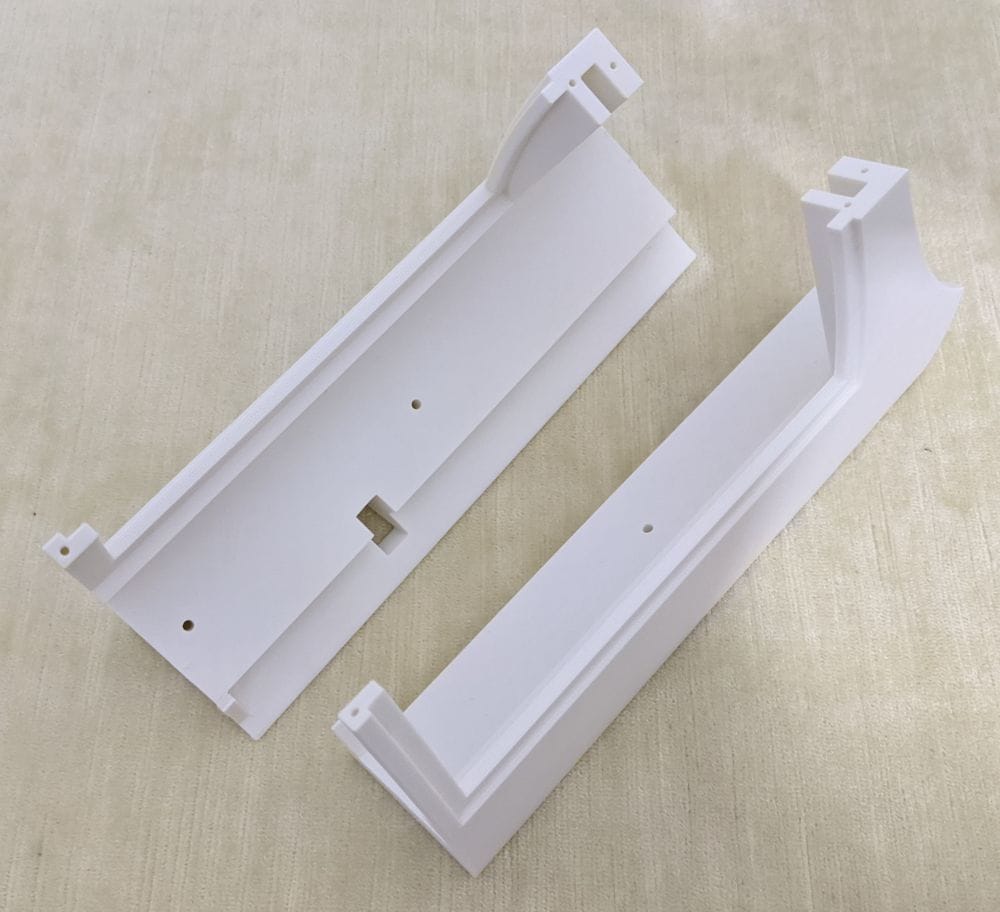
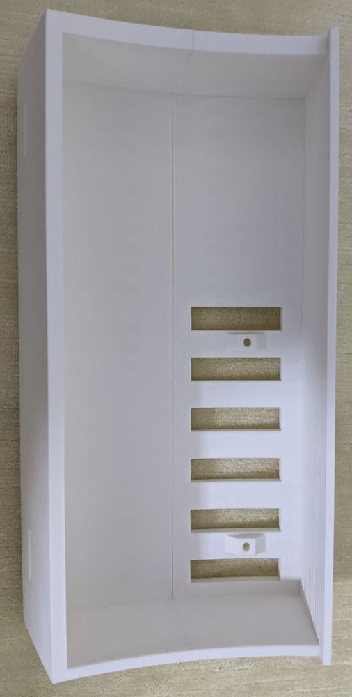
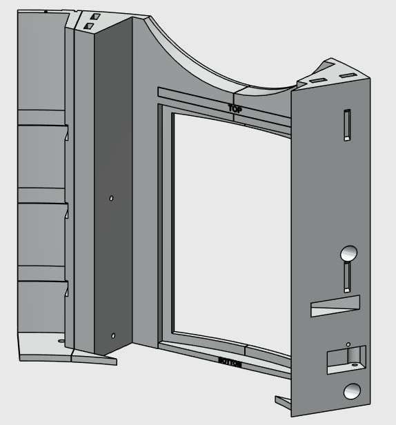
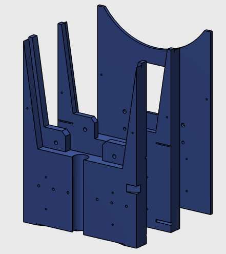
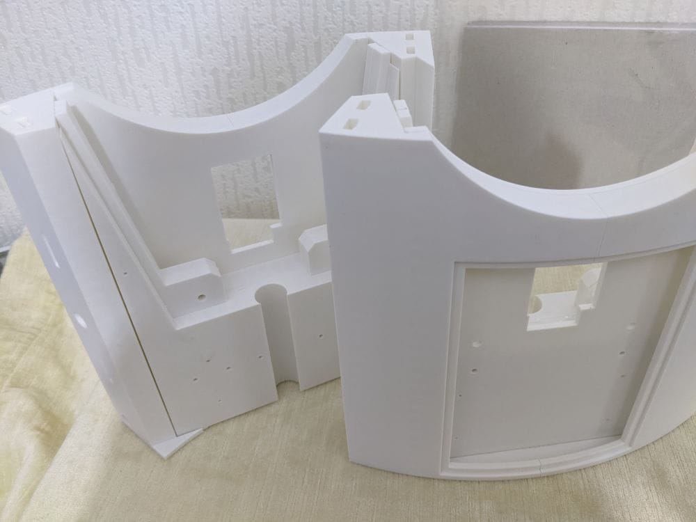
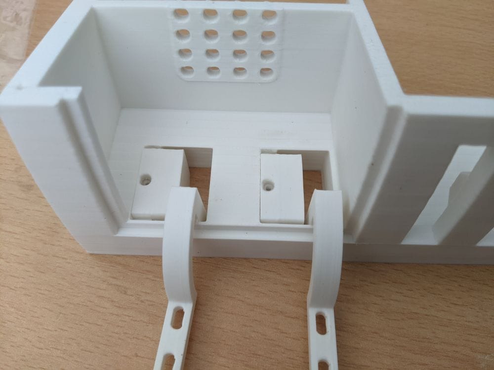
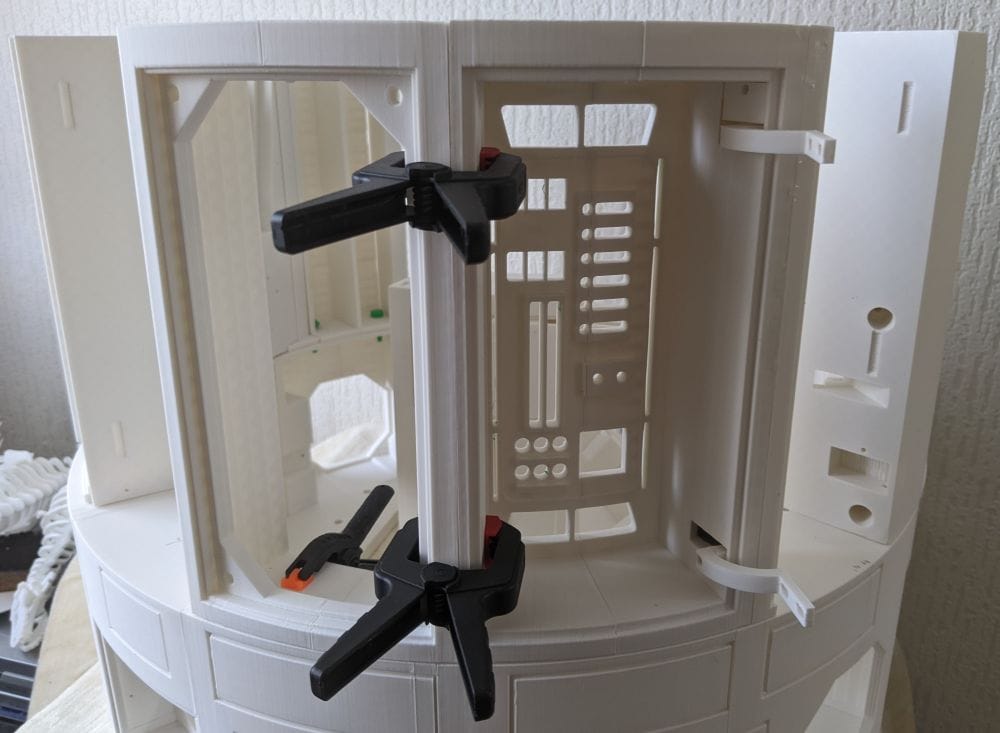
The assembly of this shoulder section is made up of seven separate parts, all glued together to form one complete unit.
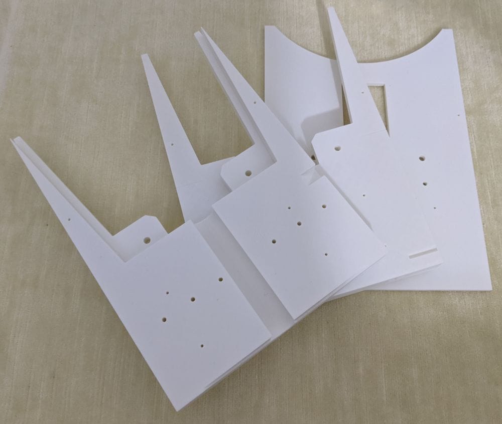
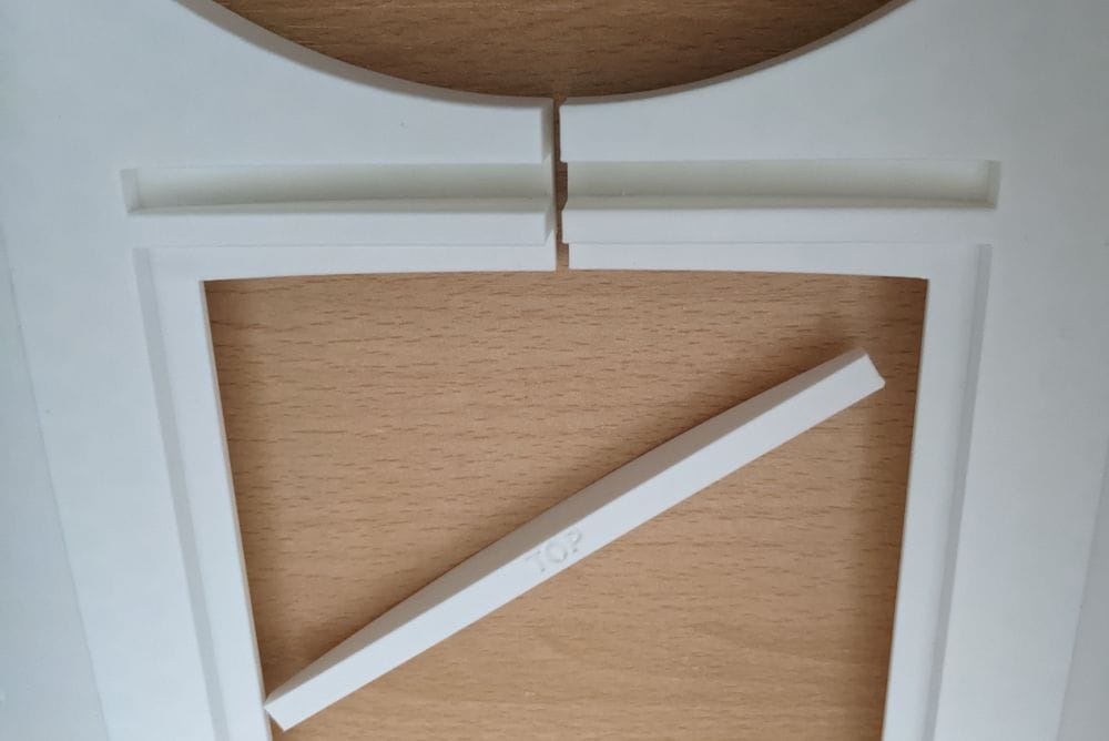
The first step is to glue the two outer sections together with the two brace pieces. Once those are secured and aligned, the three inner panels are fitted and glued into place on the inside, as shown here.
Going slowly, I test fitted each part first to check the fit and to make sure everything was the right way round. Once I was happy with the layout, I got myself set up and went through the gluing process step by step.
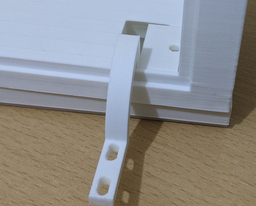
I set the two outer parts upright and glued the bottom brace to one side using the tack method, then waited for it to grab. Once that was holding, I did the same on the other outer part and waited again for the glue to take.
After it had dried enough to handle, I could move the piece around ready for the top brace. I rehearsed the glue-and-hold step first, then committed: glue in the slot, drop the brace into place, and hold it steady.
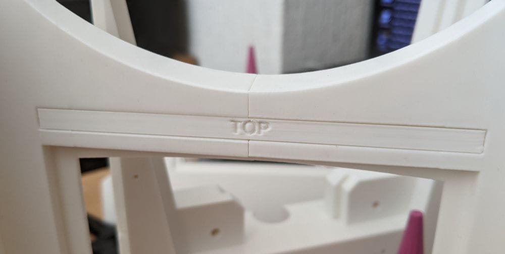
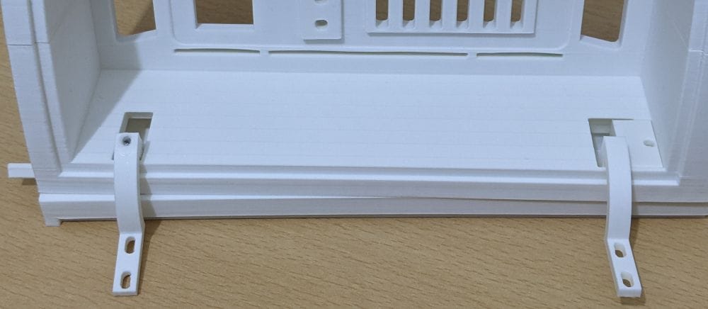
It worked well, and the first four parts were lined up and glued together.
Once dry, the three inner plates were easy to line up and glue. I used epoxy for these, mixing it on the plates before clamping each one into place.
With the first shoulder section completed, I repeated the same process for the opposite side. By this point I had a much better feel for the assembly order, so the second one went together a little more smoothly.
While waiting for the glue to set between stages, I also worked on some of the other paired parts, gluing those at the same time to make better use of the waiting periods.
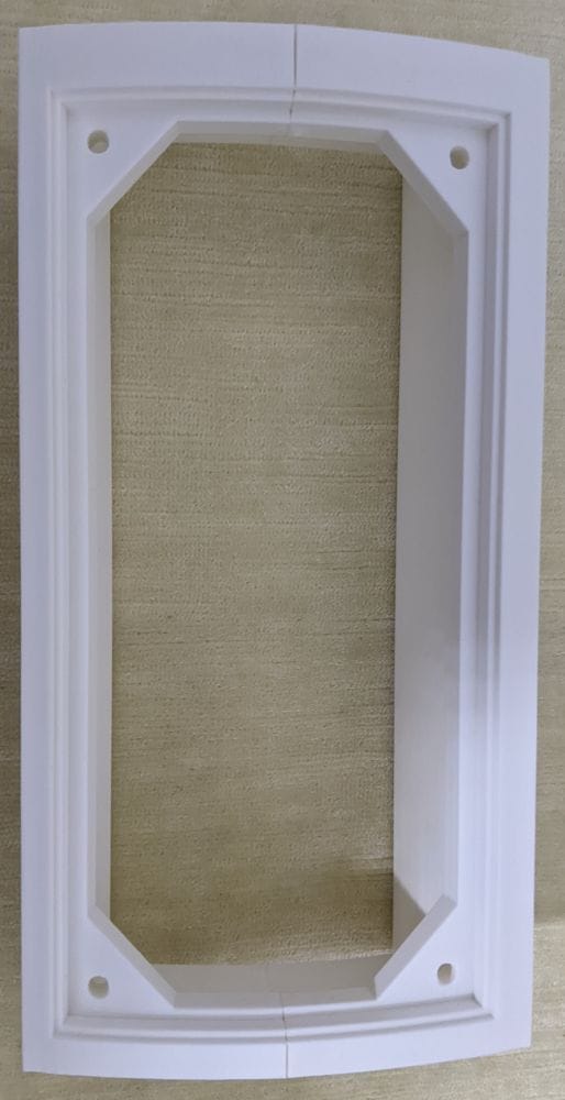
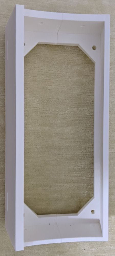
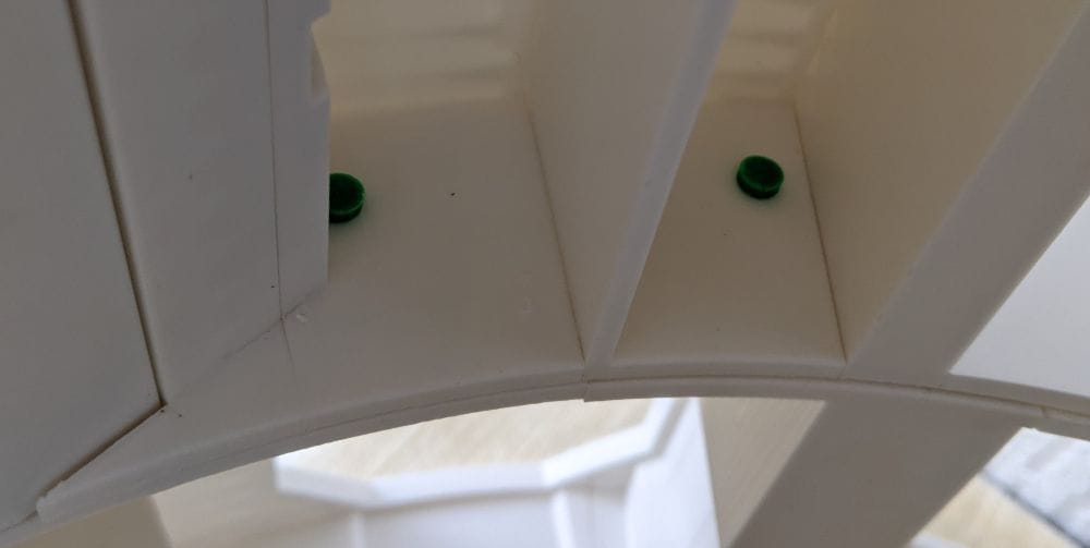
With Ring 2, some of the sections have hinges fitted to them, and a few of these need to be installed before the final gluing stage. Some of the hinges require a 3 mm peg to be glued in place for the hinge pieces to pivot on.
The recommendation was to use 3 mm steel cut to 12 mm lengths. My first thought was: where am I supposed to get 3 mm steel from?
Then it hit me — coat hangers.
I’ve got loads of them, so I went searching until I found one made from 3 mm steel wire. I cut it into small sections, and it worked perfectly.
Once the steel pins were cut, I glued them into place and test fitted the hinged parts to make sure everything lined up and moved properly before carrying on with the assembly.
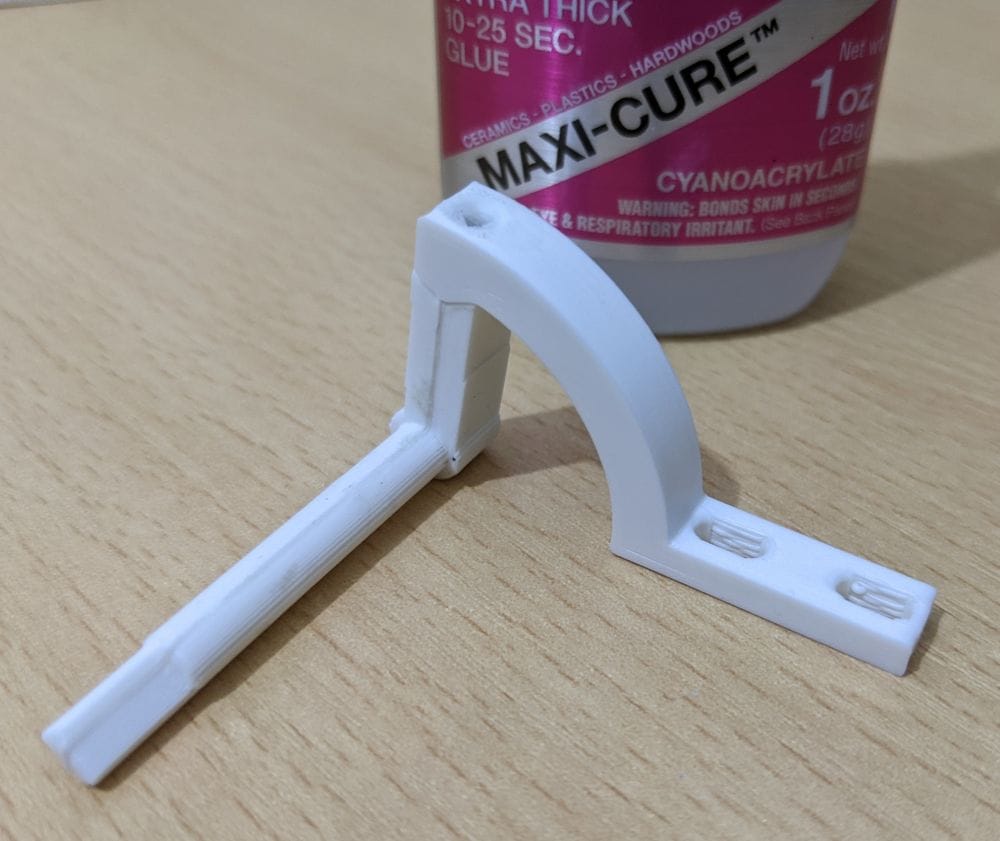
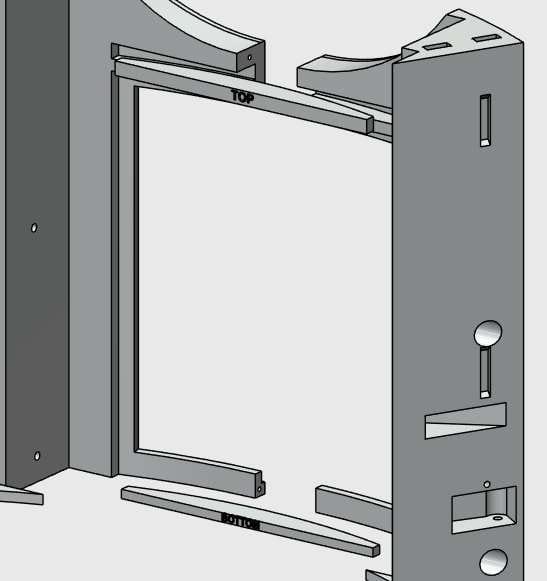
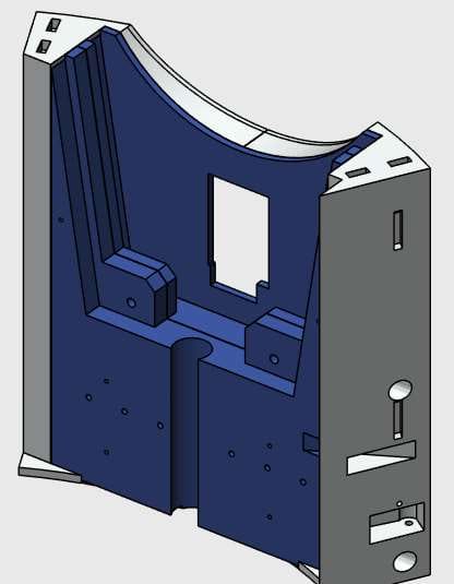
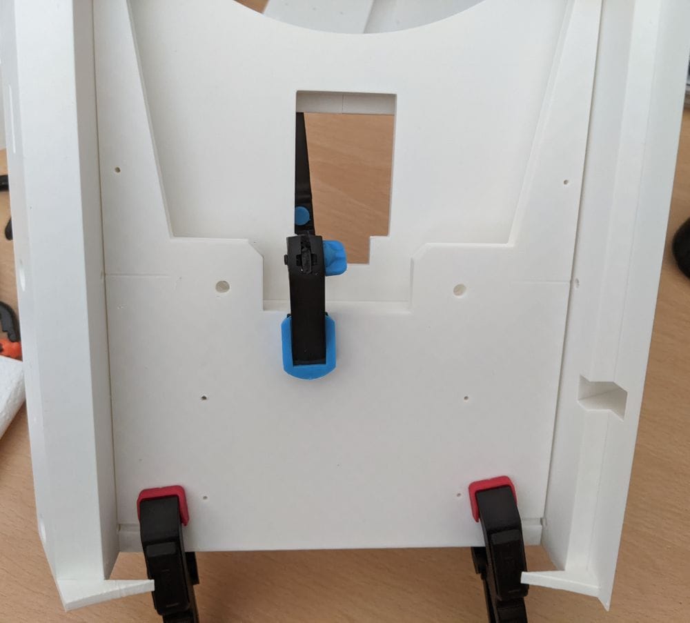
When it came to the lower hinge on this section, there was supposed to be a small piece that fitted into a slot to hold the hinge securely in place. The problem was, I couldn’t find that part anywhere in the 3D files from Patreon.
There is a video on YouTube showing the full 3D CAD model, and I could clearly see the piece I needed in the assembly, but no matter how much I searched through the files, I just couldn’t find it.
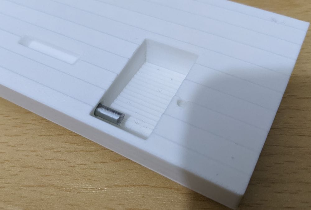
In the end, I installed Fusion 360 and downloaded the CAD files so I could dig through the model properly myself. After a bit of searching, I managed to extract the missing part and create a 3MF file ready for printing.
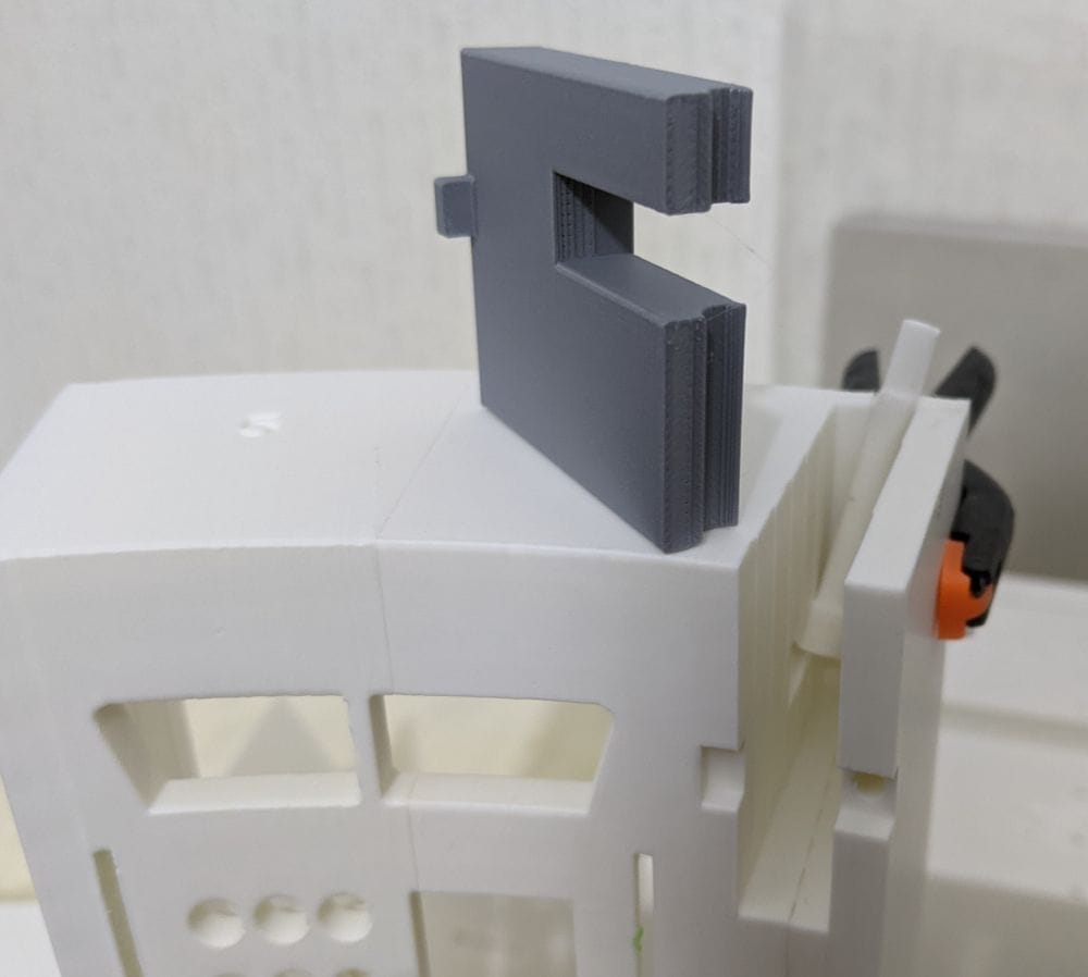
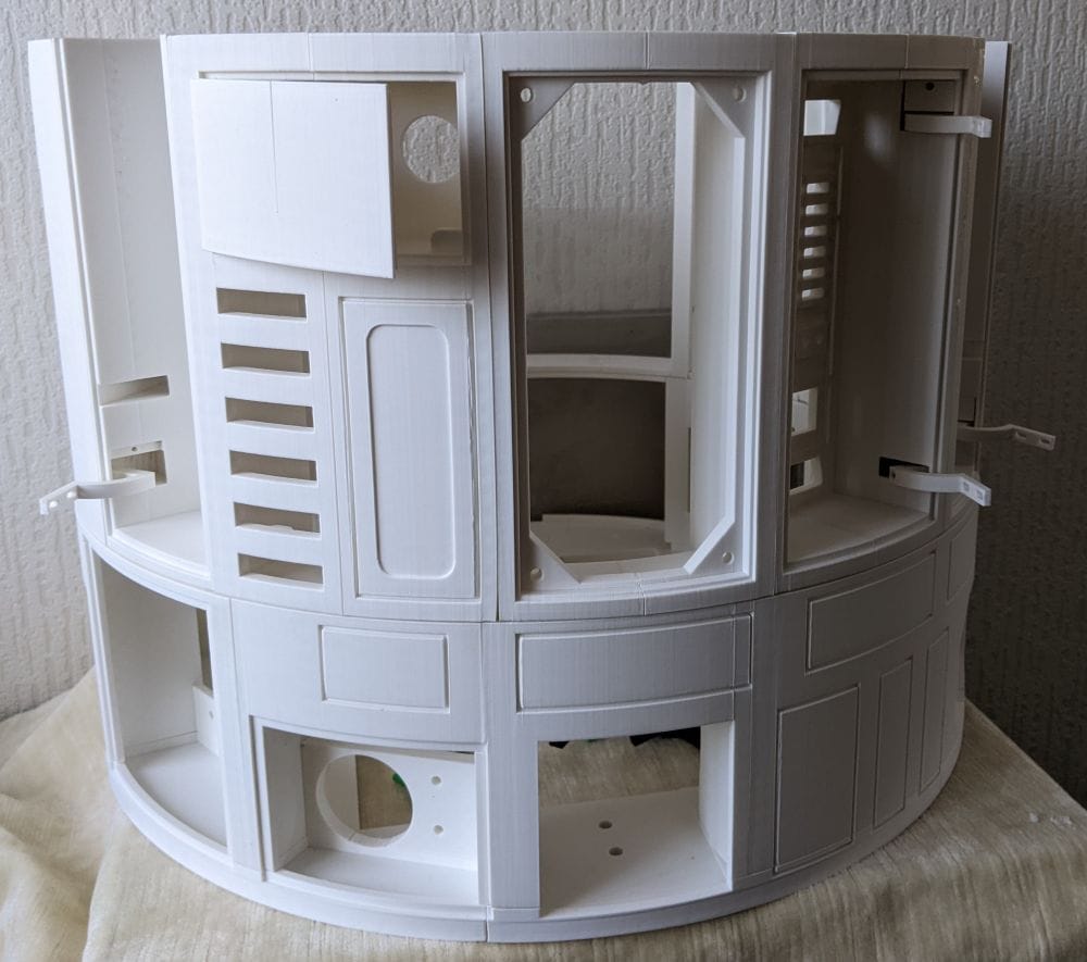
the offending part is grey.
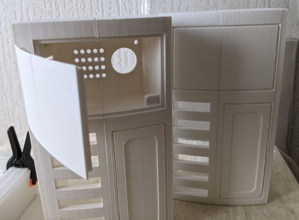
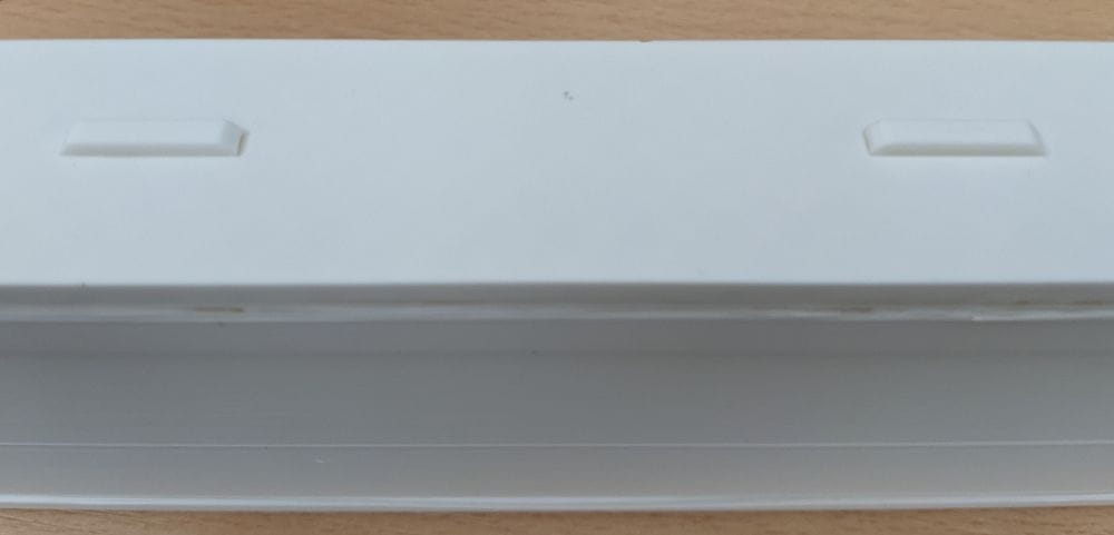
One of the paired sections I printed, MB-Ring 2-1 and MB-Ring 2-2, forms the “coin slots” section of the body. There’s also an optional modification available for this part that adds an opening door for the charge port.
It’s a slightly more involved version to print and assemble, but I decided it was worth the extra effort and went ahead with the modified version.
After gluing the two main parts together, I printed the hinges and hinge covers, fitting them using short lengths of steel rod cut from coat hangers again. This time, though, I didn’t glue the pins in place, as the hinge cover itself locks everything together once assembled.
The door itself came in two separate parts, and gluing it together turned out to be a bit fiddly. After several test fits and a bit of careful adjustment, I finally got everything lined up and glued properly.
In the end, it actually came out far better than I expected.
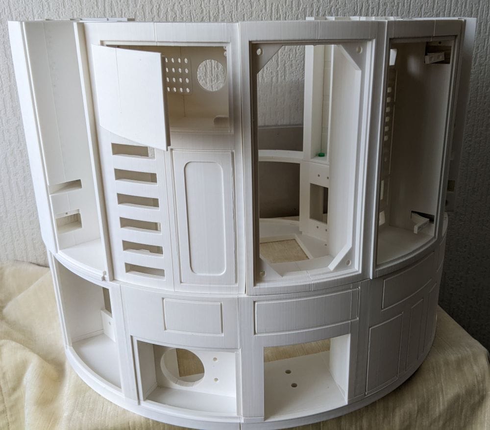
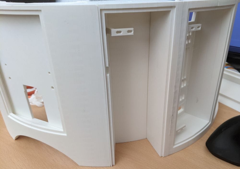
With all the Ring 2 parts finally printed, the next step was deciding the best way to assemble and glue the ring together.
Most of the paired sections had already been glued, but there were still one or two areas that would need particularly careful alignment during final assembly.
Before committing to any glue, I decided to do a full test fit on top of Ring 1 to check how everything lined up.
There are a series of 4 mm holes built into both Ring 1 and Ring 2, designed for bolts to be fitted later during the final assembly. While doing the test fit, I realised these holes could also be really useful for helping keep everything aligned while gluing.
To take advantage of that, I printed a set of simple 4 mm dowels to fit into the holes. By inserting these between Ring 1 and Ring 2 during assembly, they acted as alignment guides, helping keep the sections positioned correctly and preventing parts from shifting while I worked.
It turned out to be a simple but very effective way of making the whole fitting process a lot easier and more accurate.
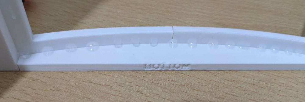
During the test fitting, I found that some of the Ring 2 sections had a slight amount of warping. Nothing too dramatic, but enough that a few areas needed pulling into alignment before they would sit properly against the neighbouring parts.
The problem was that, because of the shape of some sections, there weren’t always obvious places to attach clamps. That made the assembly a bit more awkward than earlier parts of the build.
To give myself more working time, I decided to start using epoxy rather than superglue. The slower curing time meant I could adjust the positioning and get everything lined up properly before it hardened.
I started by gluing the MB-Ring 2-3 and MB-Ring 2-4 hinge section to MB-Ring 2-6. With the help of the small connector pieces, I managed to get everything aligned and clamped into place successfully.
At first it looked like it was going well, but as the epoxy slowly settled, it began oozing out from the joins and making a bit of a mess around the seams. It gave me the working time I needed, but it also reminded me why epoxy can be frustrating on visible outer sections.
Because of that, when it came time to attach this assembly to MB-Ring 2-1 and MB-Ring 2-2, I switched back to superglue instead. The quicker grab made the process cleaner and easier to control, especially on parts where I already knew the alignment was correct from the earlier test fits.
Because of some of the slight warping in the larger sections, I found that trying to glue the entire join in one go wasn’t always the best approach.
Instead, what worked better was gluing one half of the join first and letting it fully set in place. Once that side was secure, I could gently pull the opposite side open slightly, apply the glue inside the seam, and then clamp or hold the parts tightly together until it bonded.
It turned out to be a much more controlled way of dealing with the warped sections, as it let me gradually pull the parts back into alignment rather than fighting the whole piece at once.
As the assembly progressed, I found that different sections needed slightly different approaches depending on their shape and how well they naturally lined up.
Some parts were easier to glue while sitting directly on top of Ring 1. Using Ring 1 as a support and alignment guide helped keep the shape of Ring 2 consistent while the glue set. In a few places, it also helped pull slightly warped sections back into position naturally. Once aligned, I could clamp the joins or hold them in place while everything cured.
Other sections were easier to assemble separately on the bench first before fitting them onto the ring. Smaller or more awkward parts were often simpler to line up this way, especially when clamps needed to be positioned carefully or when I needed better access to the inside seams for gluing.
In the end, the assembly became a bit of a balancing act between working on Ring 1 for alignment and building smaller sections separately where it made the process easier and more controlled.
I decided to work outward from the MB-Ring 2-1 section in both directions around the ring. On one side, I assembled and glued the sections from MB-Ring 2-1 through to MB-Ring 2-12. On the opposite side, I worked the other way around, going from MB-Ring 2-21 back to MB-Ring 2-16.
As more sections were added, I noticed the overall shape of Ring 2 was sitting slightly wider than Ring 1 in a few places. At first that was a bit worrying, especially after already dealing with some warped sections during the earlier assembly stages.
Thankfully, most of the difference turned out to be in the larger open areas that hadn’t yet been tied together by the remaining flat sections. Once I fitted and glued the final flat parts — MB-Ring 2-13, MB-Ring 2-14, and MB-Ring 2-15 — the structure immediately became much more rigid.
Those final pieces effectively pulled the whole ring together, tightening up the shape and bringing the alignment back into place. By the time everything was glued and clamped, Ring 2 fitted onto Ring 1 almost perfectly, which was a huge relief after all the earlier alignment concerns.
Ring 2 turned out to be a much bigger stage of the build than I originally expected. What started as a fairly straightforward set of printed sections quickly became a mix of support removal, warped parts, hinge assemblies, alignment problems, filament jams, missing files, and careful gluing strategies.
At times it definitely felt like one of those stages where every new step introduced a fresh problem to solve. But looking back, it was also the point where the build really started to feel like a full-sized R2 unit rather than just a collection of printed parts.
There’s still plenty left to do on Ring 2 itself. A lot of the doors, panels, and greebles still need to be printed, fitted, and adjusted, and those details will add a huge amount to the finished look of the body.
But before getting too carried away with that, there’s still Ring 3 waiting next — another large section of the build and no doubt another set of challenges to work through.