
R2-D2 Part 16: Left and Right Feet
In Part 16 of my R2-D2 build, I print and assemble the left and right feet, including the shells, battery boxes, magnets and detailed finishing parts.

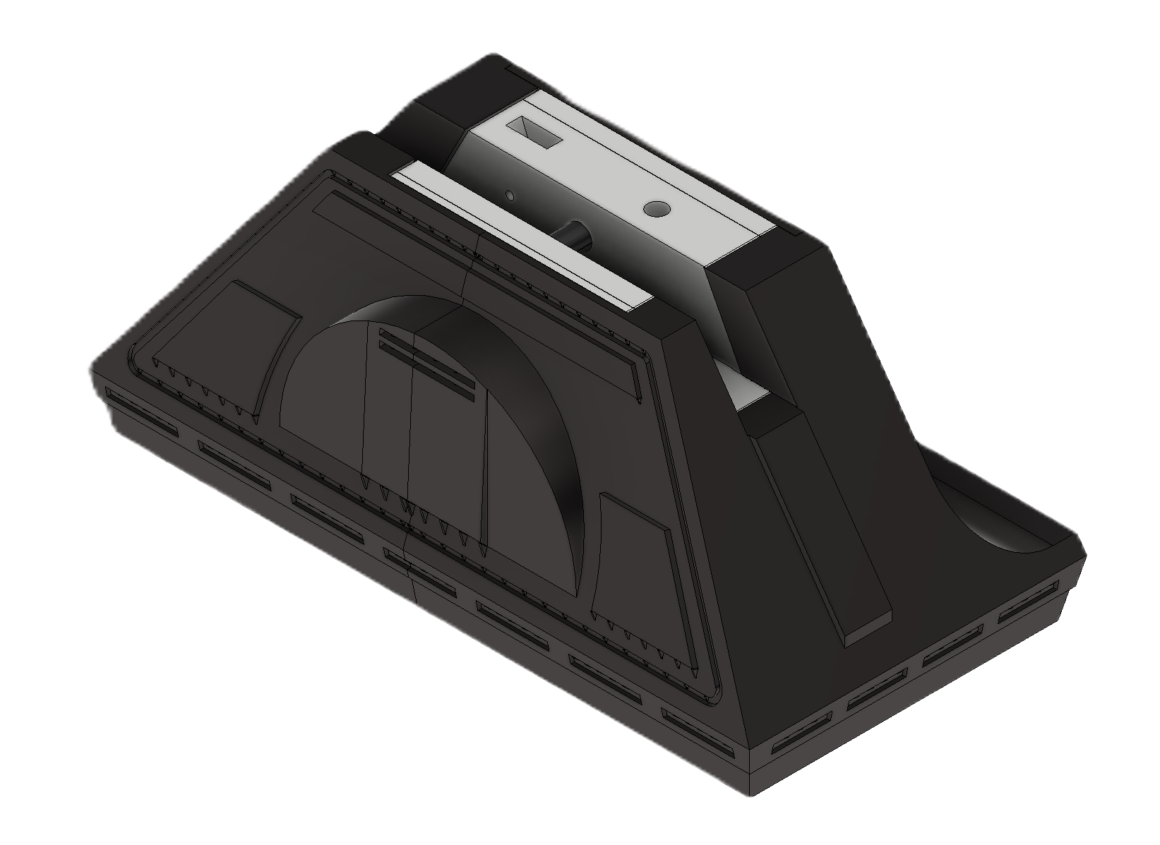
When it came to printing the left and right feet of the R2-D2 unit, I was originally planning to continue with the Version 2 model I had already been using for the rest of the build.
However, when I came to look at the available print files, I discovered that the design had moved on to Mark 3, with Version 2 now classed as a legacy version. The good news was that the Mark 3 feet were still compatible with the Version 2 legs I had already printed, so I didn't need to worry about having to reprint the legs.
I did, however, run into another problem when I looked at the outer shell of the foot. This is the largest part of the assembly, and unfortunately it was simply too large to fit on the build plate of my Bambu Lab A1.
This was a problem I'd already encountered with the centre foot, where I had to cut the large outer shell in half and print it as two separate pieces. I was prepared to do the same thing again with these feet.
Before committing to that, though, I decided to take a look at the Mark 4 version to see what had changed.
The Mark 4 feet turned out to be considerably simpler. More importantly, the parts had already been broken down into sections that would fit comfortably on my print bed. That meant I wouldn't have to modify the larger outer shell myself or deal with joining two unnecessarily large sections together.
So, after a bit of comparing between the different versions, I decided to go with the Mark 4 feet instead.
I started with the outer shell of the feet, which had already been divided into two separate parts, making them much more manageable to print on my A1.
Sometimes moving to a newer version isn't necessarily about adding more features or making the model more complicated. In this case, the Mark 4 design simply made much more sense for the printer I was using, and it saved me from having to modify the earlier version just to make it fit.
I started with the first part of the main shell, Shell A. I wasn't entirely sure how well such a large print was going to come out, so I wanted to give it the best chance possible of staying firmly attached to the build plate. I added a brim around the print, which was easy enough to remove afterwards, especially from an object this large.
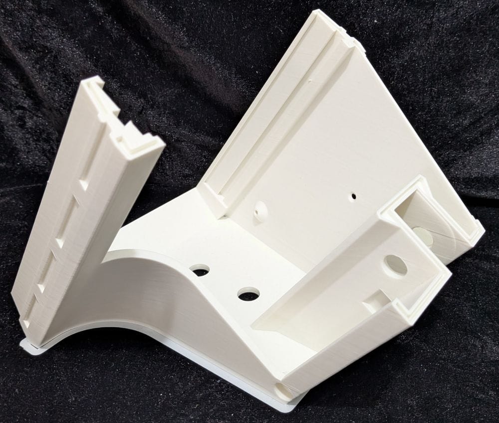
Because of its size, this was going to be a long print, taking around eight and a half hours to complete. So, with my fingers crossed, I set the printer running and waited.
To my surprise, after eight and a half hours, it came off the build plate beautifully. There were no nasty surprises, no problems with the print and nothing that needed fixing. Everything had come out just as it should.
After removing the brim, I moved straight on to the second half of the shell, Shell B. Given how well Shell A had printed, I was feeling much more confident this time around. Sure enough, it came out just as perfectly as the first half.
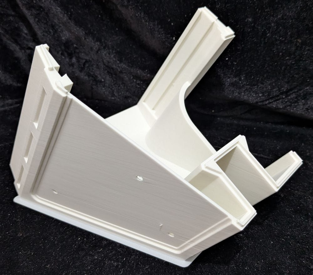
With both halves of the main shell successfully printed, I could quickly move on to the next part of the foot assembly.
Next up was Base Strip A. This is the strip that fits into the bottom of Shell A and Shell B, allowing the two halves of the main shell to slide together and lock into place.
I was a little apprehensive about how this was going to work in practice. With two large printed shells and a separate strip that needed to fit into both of them, I was expecting that I might need to do a bit of clean up or sanding to get everything to fit properly.
I printed Base Strip A with a brim again, mainly to make sure it stayed firmly attached to the build plate. Once the print was finished, I removed the brim and cleaned up the edges before trying it in the shells.
To my surprise, it fitted perfectly.
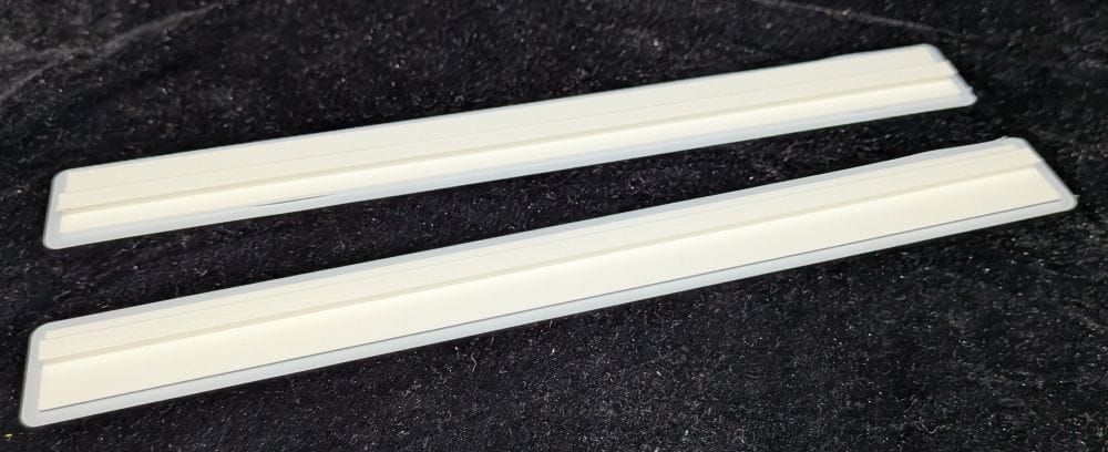
The strip simply slid into the slots in both Shell A and Shell B without any force or additional modification. I had been expecting to have to spend some time cleaning up the fit, but there was absolutely no need.
It's always a satisfying moment when a part you've been wondering about beforehand just works exactly as it should.
I quickly continued with Base Strip B, and once again, after cleaning up the edges, it fitted perfectly into the shell assembly. At this point, things were going remarkably smoothly, with every part fitting exactly as it should.
The last part of this section was the Top Frame. This was a little larger than the base strips, but still a relatively straightforward print. Once again, I used a brim to help keep the part firmly attached to the build plate and, more importantly, to prevent any curling around the edges.
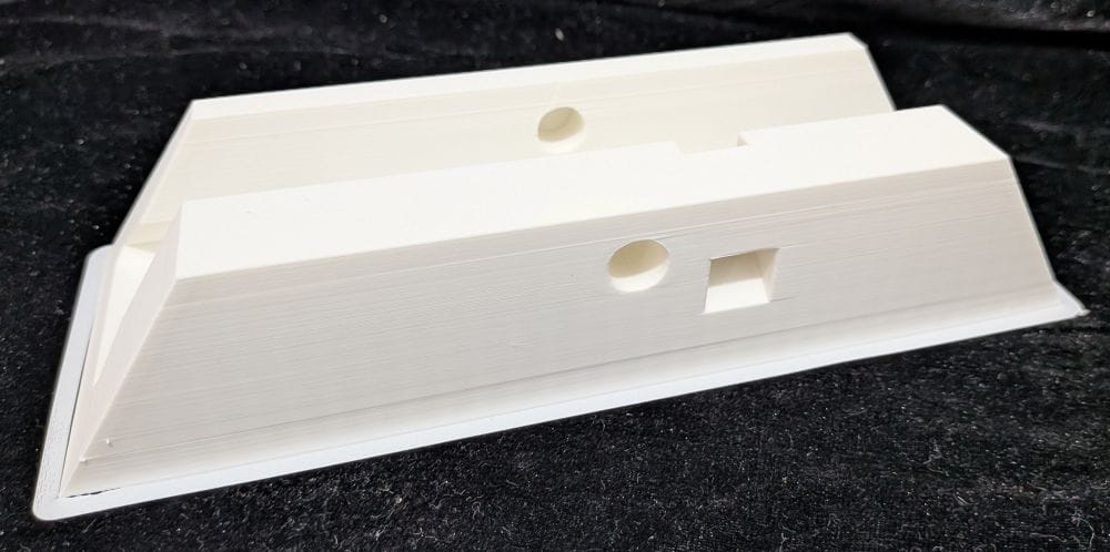
After the print had finished, I removed the brim and cleaned up the edges before trying it in the main shell assembly.
And, once again, it simply slid into place and fitted perfectly.
At this point, I was starting to wonder why I had been worrying about the fit in the first place. Everything had gone together exactly as it was supposed to — almost as if the parts had been designed to fit together, funnily enough.
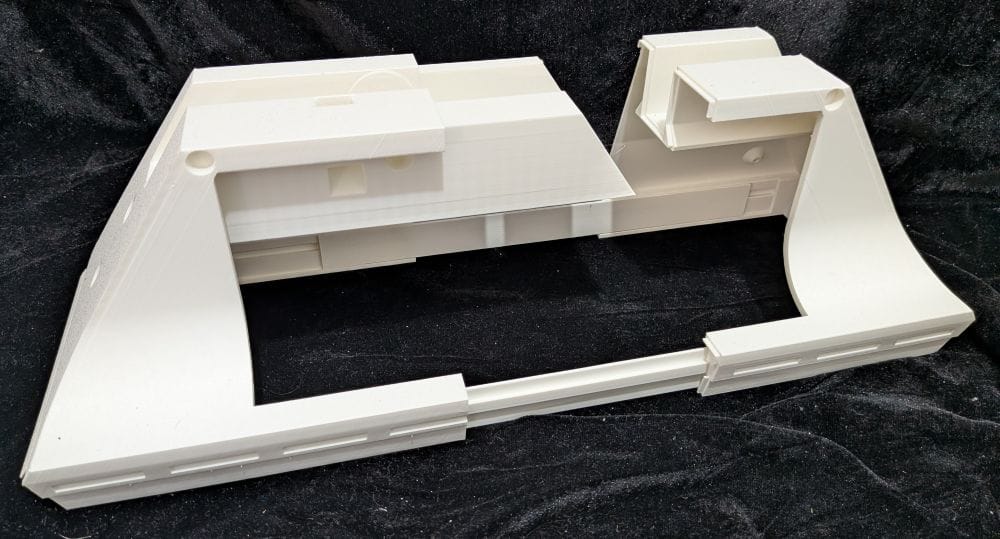
With the main shell now taking shape, I could move on to the next part of the foot assembly.
With the main shell now taking shape, I could move on to the next part of the foot assembly. But before continuing with the left foot, I decided to take the opportunity to print the exact same parts for the right foot.
There seemed little point in waiting and repeating the same process later, especially while everything was going so smoothly. Of course, there was always the possibility that something might go wrong with the second set of parts, but I was hoping everything would work out the same way.
Thankfully, it did.
The right-foot parts printed just as well as the left-foot parts, and once again everything fitted together perfectly. So far, both feet were progressing without any major problems, which was a nice change from some of the earlier parts of the R2-D2 build.
The next part to print was Shell C, the detailed plate that fits onto the main shell assembly.
There were two versions available. One was completely flat, which seemed like the obvious and simplest option, while the other was positioned at an angle with built-in supports.
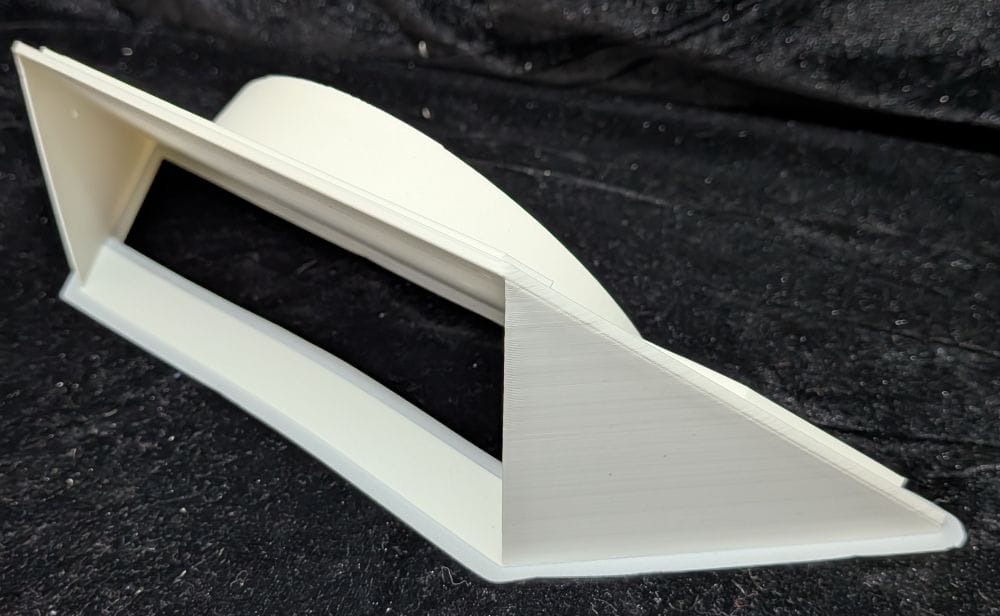
I couldn't quite understand why you would deliberately print the part at an angle rather than simply laying it flat on the build plate. So, mostly out of curiosity, I decided to try the angled version and see how it turned out.
The print went perfectly, and once it was finished and cleaned up, I was impressed with how it looked. I was still wondering why it had been designed this way, though.
It was only when I looked more closely at the finished surface that I realised the reason for the unusual orientation. Printing it at an angle gave a much better surface finish, with far less noticeable layer lines. If I had printed it flat, I expected the top surface to have the usual visible pattern from the layers.
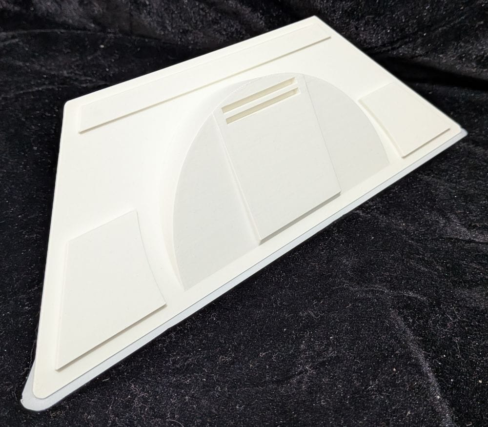
Instead, the angled print left the detailed surface looking almost smooth, and suddenly the reason for printing it this way made perfect sense.
Sometimes you don't fully appreciate a design decision until you see the finished print.
The next part I printed was a simple securing pin, which holds the foot to the ankle. The pin has a hole running through the centre. The instructions don't actually say what this is for, but I suspect it is designed to take an additional strengthening pin inside it. I'm not completely sure about that, though, so I'll have to see how it works as the build progresses.
I then moved on to the two strips that fit around the outer front and rear of the foot. These were printed in silver, along with the knurled nuts that are used on the foot and the battery box.
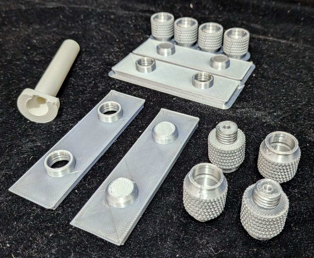
As I needed these parts for both the left and right feet, I took the opportunity to print everything together in one batch. It made sense to get them all done at the same time rather than having to run another print later for the other foot, and it saved a little time in the process.
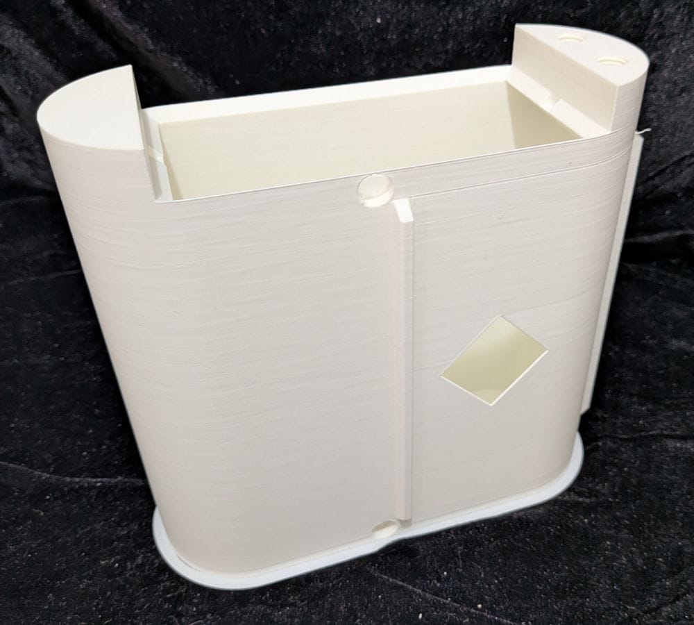
I then moved on to the battery box, starting with the main box itself. This part came with its own built-in supports, and unsurprisingly, the print came out very well.
Next was the front panel of the battery box, which is a separate part and because of the unusual shape around its edges. This one gave me a little more trouble. Even though I used a brim to help keep it attached to the build plate, the edges still curled slightly during the print.
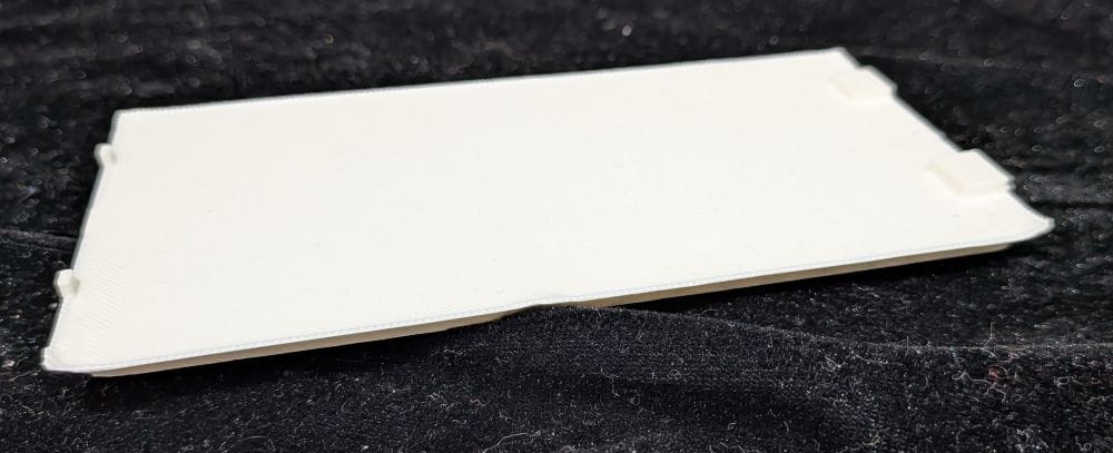
I did consider printing it again, but when I test-fitted it to the battery box, it actually fitted reasonably well despite the slight curling. In the end, I decided it was good enough and there wasn't much point in wasting another print just to try and improve something that was already going to work.
When it came to printing the battery box and separate front panel for the other foot, the results were much the same as the first set. The front panel curled slightly again, but it still fitted well enough, so I decided to leave it as it was.
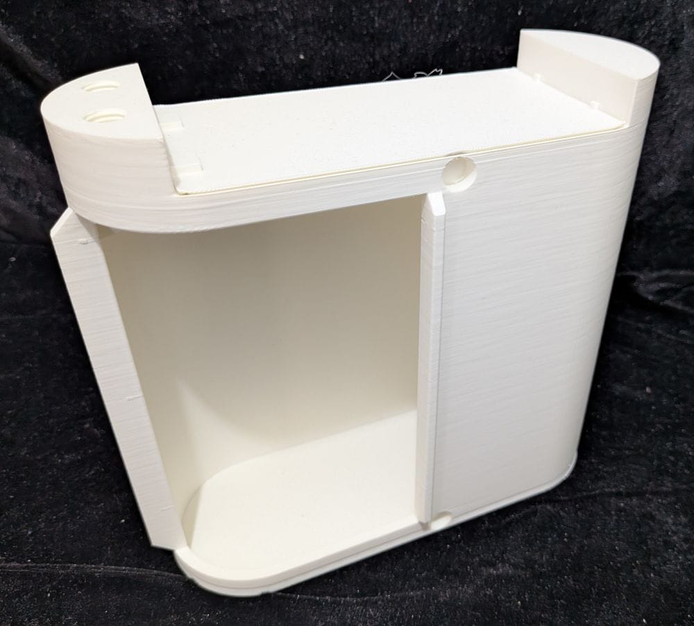
During the test fit, though, I noticed something rather unusual. The knurled nuts that screw into the battery box appeared to have the opposite thread to the ones I had just printed for the other foot.
At first, I couldn't figure out why. I wondered if there was some reason for having the threads running in opposite directions, perhaps to allow the pipework that would be attached later to be screwed in without twisting as it was tightened.
Then it dawned on me: the entire print was simply the mirror image of the other foot.
Because the battery box and its components are mirrored for the opposite side, the thread was mirrored as well. What initially looked like a strange design decision was actually just a simple consequence of making an opposite-hand version of the same part.
Another little mystery solved.
The final parts I printed for the battery box were the battery harnesses. I needed two for each battery box, and these were printed in silver.
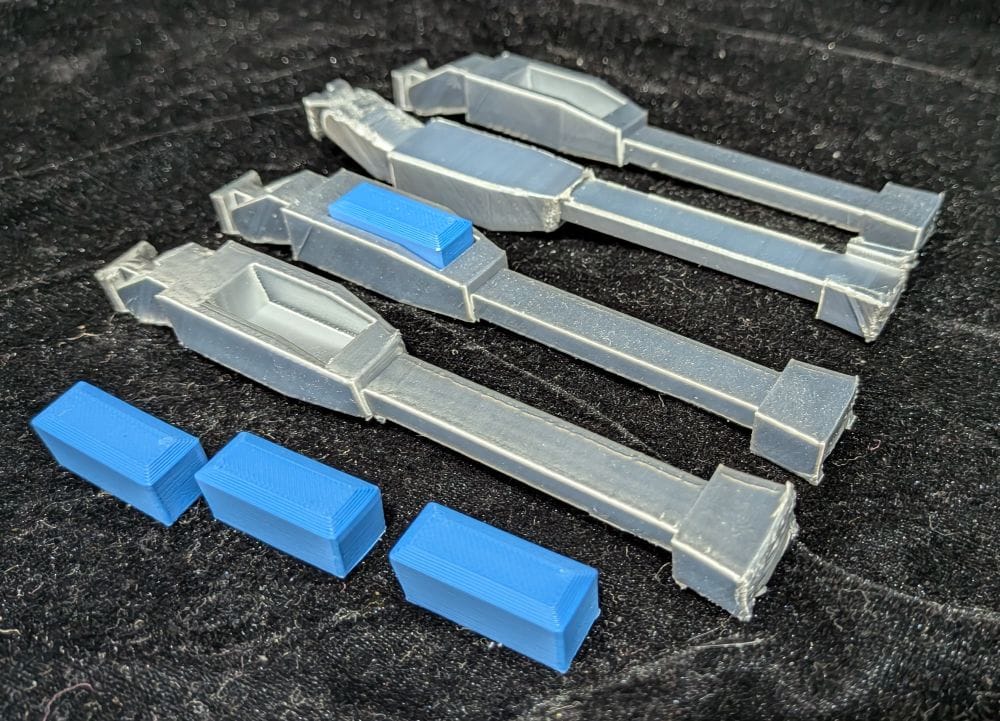
Much like Shell C, the harnesses weren't printed flat on the bed. Because of their shape, they were positioned at around a 40-degree angle with built-in supports. I assumed this was for the same reason as Shell C — to give the part a better surface finish rather than having the detailed side sitting directly on the build plate.
The prints themselves came out well, but removing the built-in supports was a bit of a pain. They were quite stubborn in places, and once removed, they left some rough edges that needed a little clean up.
The other part of the harness was the inserts, which were printed in blue. These were simply small square pieces and were very straightforward to print.
I then printed the same set of parts for the other battery box. Once everything was fitted together, I was reasonably happy with how they looked. Even though the edges of the silver harnesses weren't perfect where the supports had been removed, they fitted well and looked fine once assembled.
When it came to gluing the foot together, I had a bit of a debate with myself about the best way to approach it.
After test-fitting everything, the parts went together perfectly well, but there was a small gap between the two halves of the foot that needed to be held closed while the glue set. My initial thought was to use some bands around the foot to pull the two halves together, as I couldn't really use clamps because of the size and shape of the foot.
I tried using some elastic tape, but I quickly realised there was a problem. There were some very fragile sections at the ends of the foot, and the tension from the tape looked like it could easily damage or even break them. So that idea was quickly abandoned.
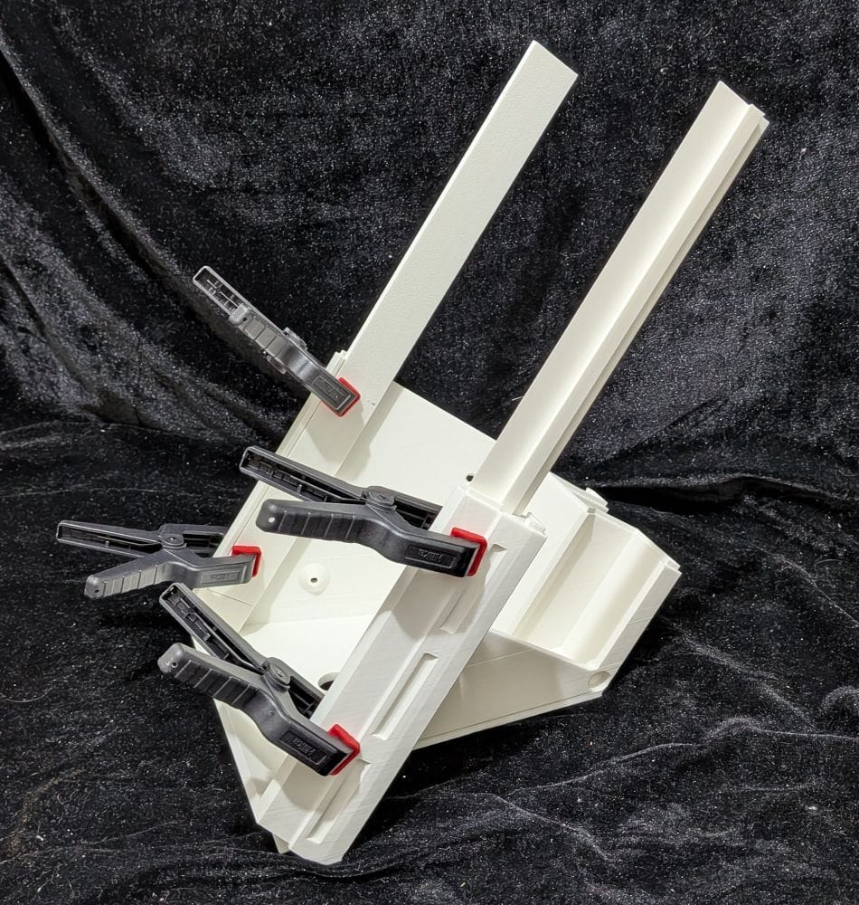
I decided to take a more controlled approach. I first glued the base strips to one side of the foot shell using Gorilla Glue Clear and left it to set overnight. The plan was to then assemble the remaining parts once those sections were firmly in place.
The following day, I applied the Gorilla Glue Clear with its longer curing time to the other areas that needed to be joined. I still had the problem of that small gap, though, and I needed some way of holding the two halves together while the glue cured.
That's when I came up with a little solution.
Rather than trying to clamp the entire foot, I used BSI Maxi-Cure super glue directly in the small gap. I applied it, pulled the two halves together by hand and simply held them in position for the minute or so that the super glue needed to cure.
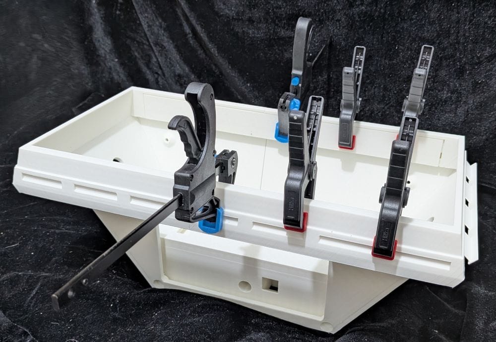
This worked surprisingly well. The Gorilla Glue Clear gave me the longer working time I needed to get everything positioned correctly, while the Maxi-Cure super glue acted almost like a quick clamp, holding the gap closed while the main glue set, I then added clamps just to be safe.
It turned out to be a much simpler solution than trying to find a way to clamp such a large and awkward-shaped part without damaging the more delicate sections.
Then I added the Shell C detail plate. The instructions call for M3 x 10mm grub screws to help with alignment, but as I'd done on previous parts of the build, I decided to use my own method instead.
I used tightly rolled-up pieces of paper as locating pins, which worked surprisingly well. They allowed me to get everything lined up correctly before applying the glue, without having to use the grub screws.
Once everything was aligned, I glued the detail plate into place and left it to set.
I also took the remaining parts for the battery boxes for both the left and right feet and glued them together. Surprisingly, they went together really well, and I was quite pleased with how they turned out. It was another straightforward assembly, and I was happy with the finished result.
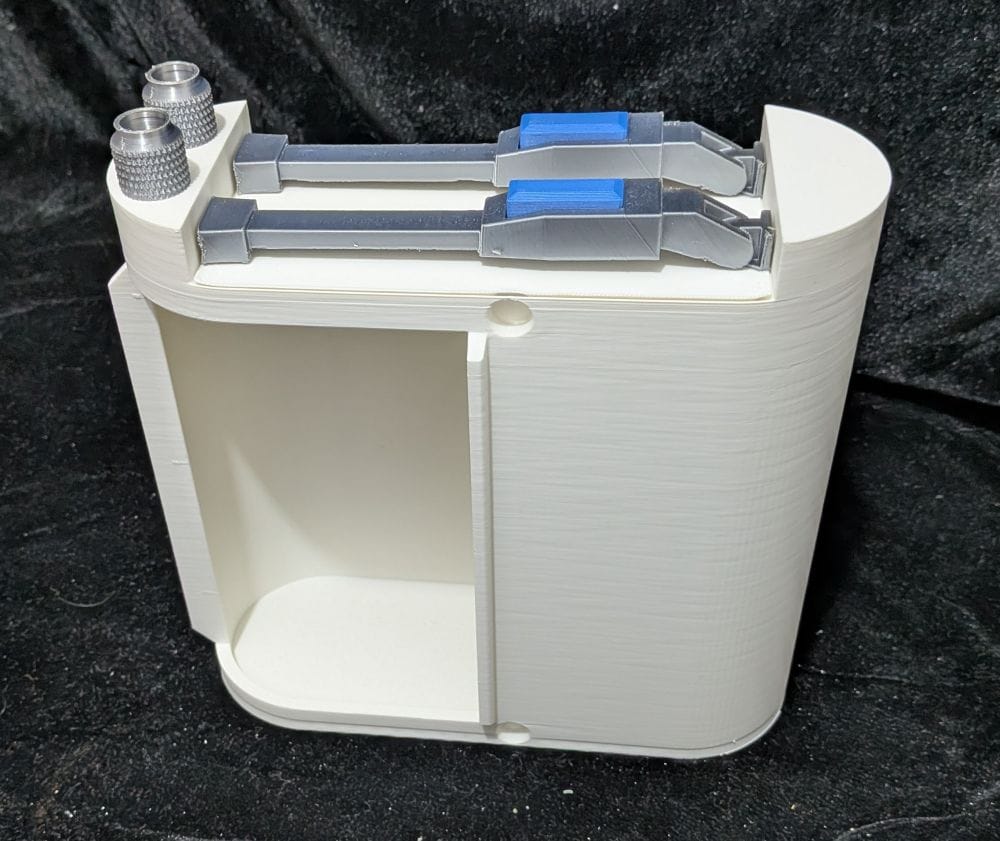
Next it was time to add the magnets. As with the other parts of the build, I made sure to check the polarity carefully before gluing them into place. Getting this wrong would have been rather annoying, especially once everything else was assembled.
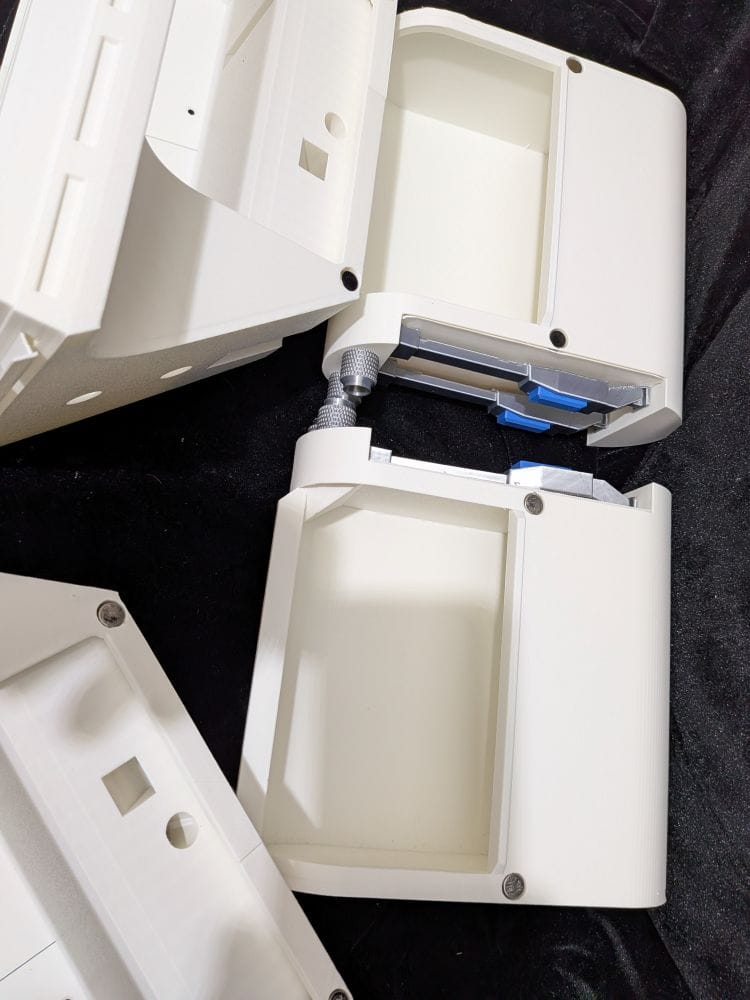
Once I had the foot fully assembled and glued, I added the silver strips to the front and rear.
I had to make sure I fitted these the correct way around, particularly because of the cabling that would eventually run from the foot to the battery box. Rather than relying on the instructions, I also checked pictures of the real R2-D2 unit to make sure I had the orientation right.
It might seem like a small detail, but getting this wrong would have been a shame after putting all the work into the rest of the foot, so it was worth taking the time to check before gluing them into place.
With both feet assembled, I was then left with another little dilemma: what to use for the hose pipes running from the feet to the battery boxes.
I'd seen a few different approaches on various websites. Some people had 3D-printed them in TPU, while others had bought suitable tubing instead. There seemed to be several ways of doing it, but I hadn't decided which route I was going to take yet.
So, for now, the feet were complete, but the hoses would have to wait until I had worked out exactly what I wanted to use.
I then had a thought about the hoses that run from the feet to the battery boxes. I remembered that we had some flexible conduit at work, although I was fairly sure it was going to be far too large for the job.
The following day, while I was at work, I went looking for it and, to my surprise, it was much smaller than I had remembered. I thought it might actually be the right size.
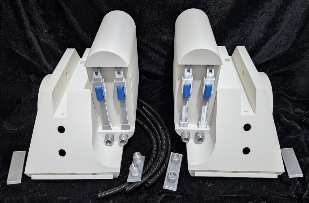
There was one problem, though: it was split conduit. I wasn't sure how well that was going to work, but I thought it was worth trying. It was also black, whereas the hoses on the real R2-D2 are silver, but I wanted to see how it looked before dismissing the idea.
I cut four lengths that I could use, figuring that if it didn't work, I'd simply throw them away. So, I liberated four pieces from work and took them home.
Once home, I tried them on the knurled nuts on the battery boxes, and they fitted perfectly. I then worked out that the correct length was 12 inches, so I cut each piece to length and fitted them into position to see how they looked.
I was pleasantly surprised.
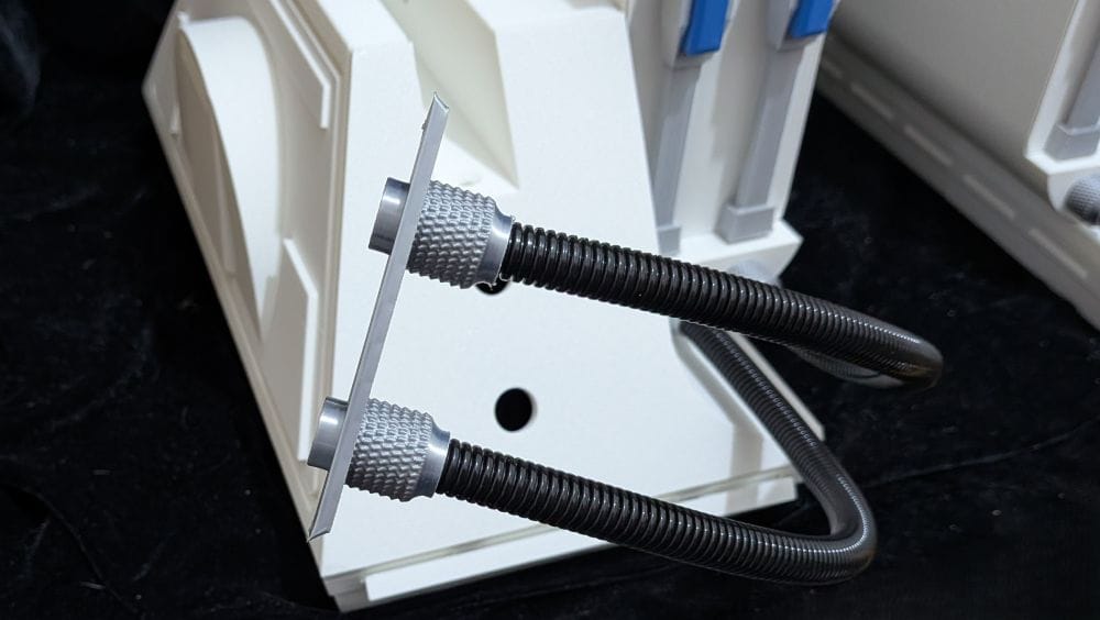
I had expected the split in the conduit to be a problem, but because it is wound so tightly together, you can barely notice it once it's fitted. The fact that it's black also helps disguise the split, and overall it looked much better than I had expected.
Getting it glued into the feet, however, turned out to be a bit of a challenge. For some reason, the superglue simply wouldn't take, and I had to try several times before I finally managed to get it to cure and hold the conduit securely in place. It took quite a bit of time and patience, but eventually I got there. It wasn't quite as flexible as I had originally hoped, but I was pleased that my idea of using the conduit had worked.
When it came to the drive wheels for the feet, there were three options available in the design, depending on how the R2-D2 was going to be used.
One option was the Suspension Drive, which was designed to work with either 4-inch or 3.25-inch VEX Omniwheels. This included full suspension, provided a higher ride height, and used a clip-in arrangement so the drive system could be easily removed for maintenance. It was also relatively simple to construct.
The other option was the Static Frame, which was a much simpler arrangement intended for a static display. One of the advantages was that it could easily be swapped out for one of the other drive systems later.
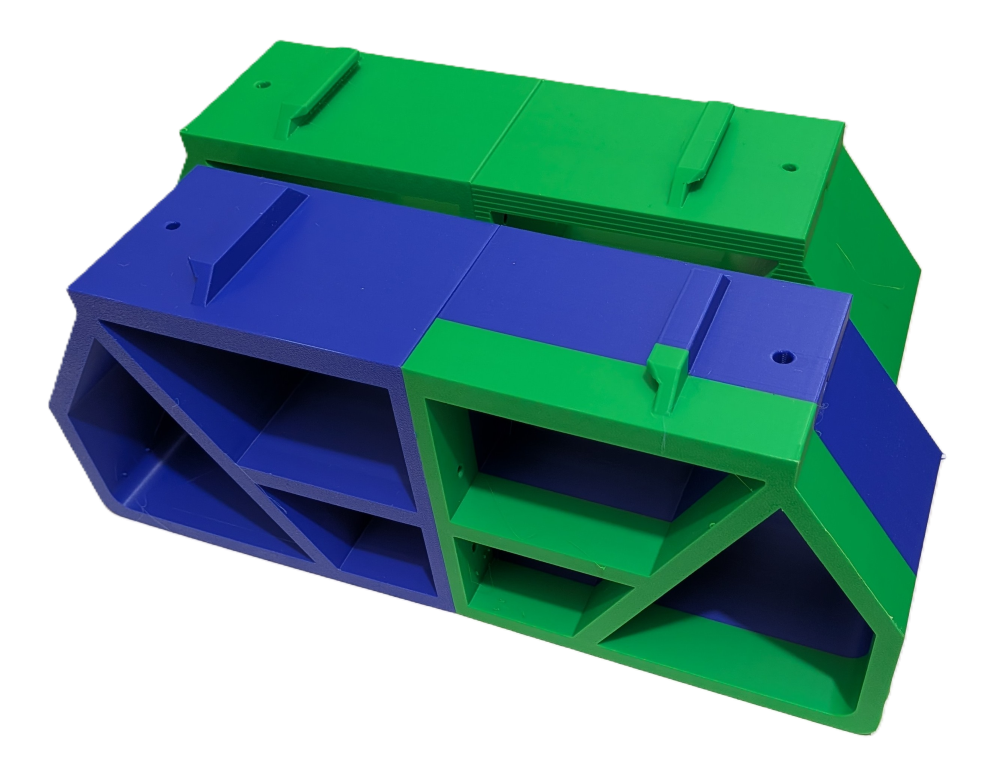
For now, I decided to go with the Static Frame. As these parts would be hidden inside the feet anyway, I simply printed them using whatever spare filament I had available. There seemed little point in using my more expensive filament on parts that would never be seen.